


High-frequency
vibration sensor. Machine vibration.
Connected to your team.

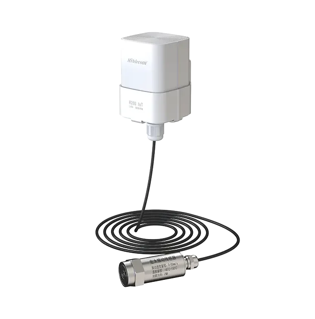
Hitelecom H Series vibration terminal with black external-probe cable and metal vibration probe, official product image
Official product image · Cabled vibration probe

The Hitelecom H Series vibration sensor combines a cabled external probe with a wireless terminal for high-frequency machinery monitoring. Mount the probe on a rigid motor bearing-housing point and send configured readings to your maintenance team. Select single-axis or triaxial sensing, with a vibration velocity RMS range of 0–50 mm/s, a display resolution of 0.1 mm/s and a measurement frequency range of 10–5,000 Hz. Match 4G, NB-IoT or LoRa connectivity and the reporting profile to your installation.

0–50 mm/sVibration velocity RMS0.1 mm/s display resolution
10–5,000 HzMeasurement frequency rangeSingle-axis or triaxial configuration
IP68Enclosure ratingProbe, cable and mounting selected for the site

KEY FEATURES

Machine vibration.
Connected to maintenance.

Bring a machine-mounted probe, a suitable measurement profile and a wireless data connection into one monitoring workflow.

Probe at the machine

Place the cabled external probe at the selected mechanical point while locating the terminal for practical access and radio coverage.

Vibration velocity RMS

Measure vibration velocity RMS from 0–50 mm/s with a display resolution of 0.1 mm/s. Choose single-axis or triaxial sensing for the machine and measurement objective.

10–5,000 Hz measurement range

Monitor machinery vibration within a 10–5,000 Hz measurement frequency range. Match the probe mounting and acquisition profile to the frequencies relevant to your equipment.

Wireless remote reporting

Use the supplied 4G, NB-IoT or LoRa variant to connect distributed measurement points to the agreed monitoring platform.

Configured alert workflow

Define project thresholds, notification recipients and the inspection response around the selected metric and normal operating conditions.

Practical device setup

NFC activation, local configuration and OTA updates are listed for the family. Confirm the functions available on the supplied model.

MEASURE THE RIGHT QUANTITY

A clear quantity.
A repeatable measurement point.

A useful machine trend starts with a repeatable point, a clearly defined value and the operating conditions behind it. Agree these together before selecting the probe and reporting profile.

01

Vibration velocity RMS

Root mean square (RMS) vibration velocity is expressed in mm/s. The measurement range is 0–50 mm/s, with a display resolution of 0.1 mm/s. Compare readings at the same machine point under comparable operating conditions.

Define your measurement
Single-axis or triaxial · Mounting point · Operating speed · Normal baseline
Discuss this measurement ↗
02

Measurement frequency range

The specified measurement frequency range is 10–5,000 Hz. This describes the vibration frequencies measured by the probe; choose the wireless reporting interval separately to suit your maintenance workflow.

Define your measurement
Relevant machine frequencies · Probe mounting · Acquisition profile · Reporting interval
Discuss this measurement ↗
03

Operating context

Machine speed, load and production stage give each comparison its context. Capture these in the monitoring plan or available site records.

Share your operating context
RPM range · Load state · Production cycle · Normal baseline
Discuss your machine ↗
SENSING & INSTALLATION

Probe on the machine.
Terminal at a suitable location.

Mount the external probe directly on an approved rigid motor bearing housing or end-shield measurement pad near the selected bearing. Choose the sensing direction for a single-axis configuration, or define the three-axis orientation for a triaxial configuration. Secure the probe cable with suitable strain relief, clear of rotating parts and hot surfaces. Mount the wireless terminal separately within its environmental limits and verify coverage at that position. Follow the supplied probe mounting method, cable specification and installation drawing.

Motor-mounted vibration probe and separate wireless terminal The external vibration probe is mounted directly on a rigid pad on the motor bearing end shield. A secured cable runs to a separate terminal, which communicates wirelessly to the Hitelecom platform. This is a mounting principle, not a dimensioned installation drawing. Motor bearing-housing pointMotor-mounted probeSecured probe cableSeparate terminalWireless linkHitelecom Platform
  1. 01 Motor-mounted probe
  2. 02 Secured cable route
  3. 03 Separate terminal
  4. 04 Hitelecom platform link
Installation principle: the probe is mounted on a rigid motor bearing-housing point, with secured cable routing to a separately mounted wireless terminal.

FROM READING TO RESPONSE

Measure at the machine.
Report to your team.

Acquisition defines how vibration is measured; reporting defines when the terminal sends data. Set the measurement band, acquisition requirements, reporting interval and alert response as one operating profile.

01

Measure

The external probe measures at the labelled machine point. Match the supplied measurement quantity, frequency band and acquisition settings to the monitoring objective.

02

Report

The terminal sends the configured readings through the selected cellular or LoRa connection. Agree the reporting schedule and complete platform path.

03

Review & respond

Compare like operating states, review configured notifications and give the maintenance team an agreed inspection step. Record the result for the next comparison.

PUBLISHED BATTERY-LIFE DESIGNOver 10 years.
At one-hour reporting.

The published battery-life reference exceeds 10 years at one-hour reporting under specified conditions. This reference belongs to the configured terminal operating profile. Actual life depends on the supplied battery, probe and acquisition duty, reporting schedule, radio coverage, retransmissions and temperature. Request the life estimate for the complete configuration you intend to deploy.

APPLICATIONS

Machinery across your operation.
A clear point for every project.

Explore 48 practical monitoring tasks across eight machinery families. Each task identifies a fixed probe point, the operating context to compare and the details that help specify a suitable configuration.

8 machinery families 48 monitoring tasks

Photos illustrate machinery environments. Select the actual point, probe band and installation with your machine engineer.
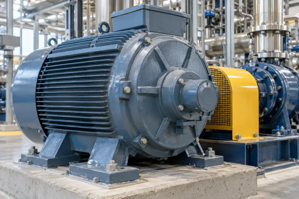
01Electric motors & factory drives6 monitoring tasks
Electric motor bearing housing with a rigid stationary end shield
Motor bearing-housing environment · Illustrative scene

Compare vibration trends at selected fixed motor measurement points across production lines, power packs and rotating drive systems.

Production-line electric motors

Local machinery vibration at a defined fixed point
Electric motor bearing housing with a rigid stationary end shield
Motor bearing-housing environment · Illustrative scene

Track changes at a motor's bearing housing and give maintenance teams a repeatable reference for routine inspection.

Measurement focus
Local machinery vibration at a defined fixed point
Probe mounting point
Fixed motor end shield near the drive-end bearing.
Installation planning
Use an approved rigid point, document the sensing direction, and route the probe cable outside the coupling guard.
Project brief
Motor rating, RPM, load pattern, bearing positions and a mounting photo.
Discuss this application

Variable-speed motor drives

Local machinery vibration at a defined fixed point
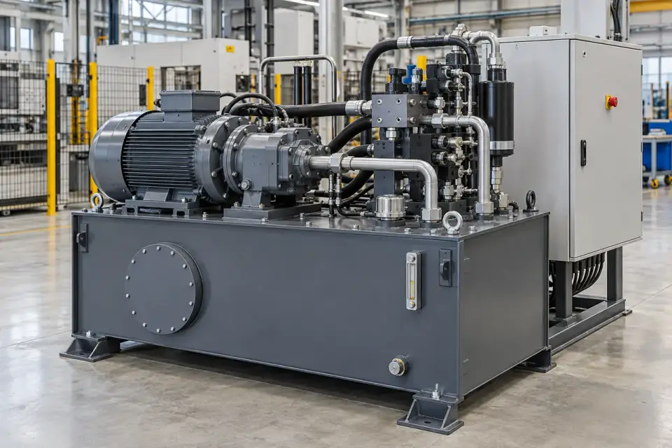
Electric motor bearing housing with a rigid stationary end shield
Motor bearing-housing environment · Illustrative scene

Compare readings within matching speed and load windows so normal changes in operating duty remain visible in the trend.
Measurement focus
Local machinery vibration at a defined fixed point
Probe mounting point
Accessible drive-end or non-drive-end bearing housing.
Installation planning
Identify operating-speed bands before defining a baseline and keep the sensing position consistent after maintenance.
Project brief
Speed range, operating states, duty cycle and the data available from the drive.
Discuss this application

Hydraulic power-pack motors

Local machinery vibration at a defined fixed point
Hydraulic power pack with an electric motor and pump mounted above a reservoir
Hydraulic power-pack environment · Illustrative scene

Observe the electric motor that drives a hydraulic power unit and support checks during comparable pressure-demand cycles.

Measurement focus
Local machinery vibration at a defined fixed point
Probe mounting point
Motor bearing housing on the stationary power-pack assembly.
Installation planning
Record pump load and motor duty; mount the probe to the motor rather than the reservoir sheet metal.
Project brief
Power-pack layout, motor speed, hydraulic operating cycle and cable route.
Discuss this application

Injection-moulding hydraulic drives

Local machinery vibration at a defined fixed point
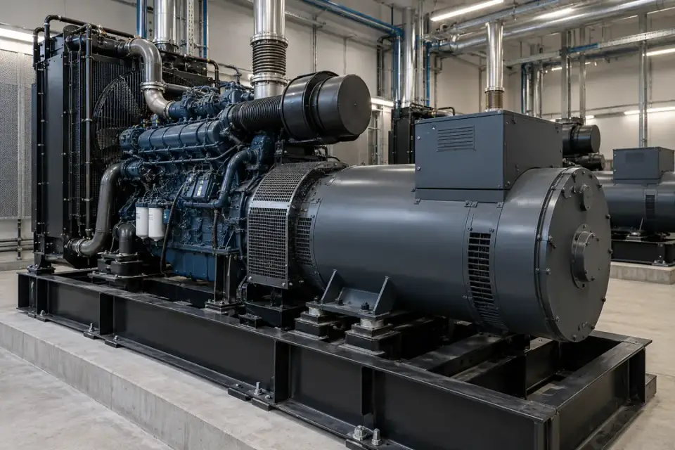
Hydraulic power pack with an electric motor and pump mounted above a reservoir
Hydraulic power-pack environment · Illustrative scene

Follow motor-side vibration through repeatable moulding cycles and help prioritise drive inspection alongside production records.
Measurement focus
Local machinery vibration at a defined fixed point
Probe mounting point
Fixed bearing region of the hydraulic-drive motor.
Installation planning
Choose an accessible stationary point and compare the same cycle phase, avoiding hoses and removable guards.
Project brief
Machine type, drive arrangement, cycle stages and maintenance access.
Discuss this application

Generator alternator bearings

Local machinery vibration at a defined fixed point
Industrial generator and alternator with accessible stationary bearing housings
Generator and alternator environment · Illustrative scene

Build a vibration history for a generator's rotating electrical machine at defined operating load and speed.

Measurement focus
Local machinery vibration at a defined fixed point
Probe mounting point
Accessible fixed alternator bearing housing.
Installation planning
Separate alternator monitoring from engine-frame vibration and confirm permissible temperature, range and cable protection.
Project brief
Alternator layout, normal speed, load range and environmental conditions.
Discuss this application

Motor end-of-line test benches

Local machinery vibration at a defined fixed point
Electric motor bearing housing with a rigid stationary end shield
Motor bearing-housing environment · Illustrative scene

Record comparable vibration readings during a defined run test to support an agreed inspection or acceptance workflow.
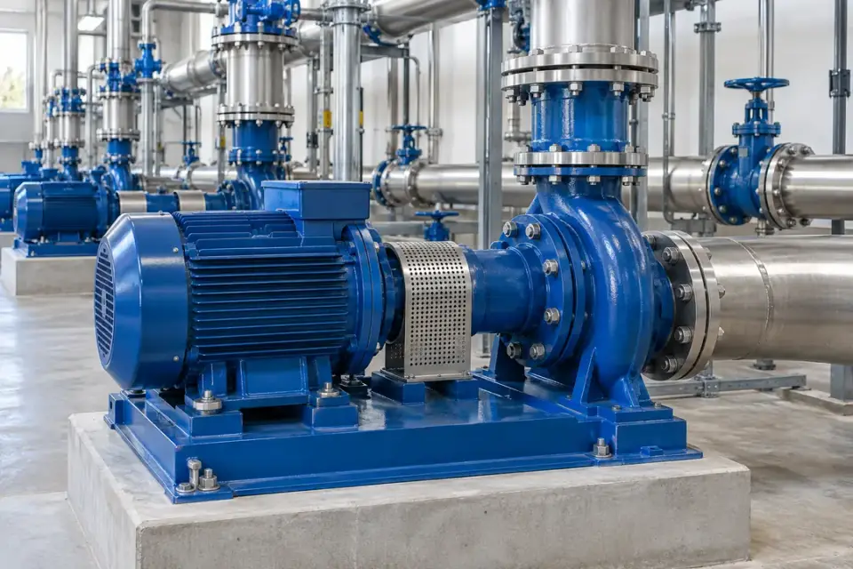
Measurement focus
Local machinery vibration at a defined fixed point
Probe mounting point
A repeatable rigid point on the test motor housing.
Installation planning
Fix the speed, load and mounting method in the test procedure; use acceptance limits approved for the motor.
Project brief
Test sequence, expected amplitude, required metric and repeatable fixture layout.
Discuss this application
02Pumps & water systems6 monitoring tasks
Dry-mounted centrifugal pumps and motor drives at a water pumping station
Water-pump machinery environment · Illustrative scene

Place the probe near the motor or pump bearing path and relate changes to flow, pressure and operating duty.

Municipal water booster pumps

Local machinery vibration at a defined fixed point
Dry-mounted centrifugal pumps and motor drives at a water pumping station
Water-pump machinery environment · Illustrative scene

Track selected motor and pump points across duty and standby units to support maintenance planning at pumping stations.
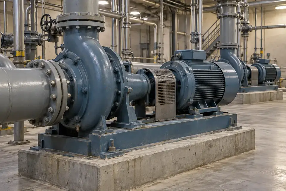
Measurement focus
Local machinery vibration at a defined fixed point
Probe mounting point
Stationary motor end shield or accessible pump bearing housing.
Installation planning
Label each point separately and compare like operating conditions; keep cable loops clear of couplings.
Project brief
Pump layout, speed, flow/pressure duty and the number of monitoring points.
Discuss this application

Wastewater pumping-station drives

Local machinery vibration at a defined fixed point
Dry wastewater pump assemblies with accessible motor and bearing regions
Dry wastewater pump environment · Illustrative scene

Observe accessible dry-mounted pump and motor assemblies and compare trends alongside pumping-cycle records.
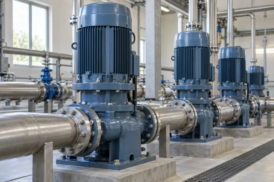
Measurement focus
Local machinery vibration at a defined fixed point
Probe mounting point
Dry accessible motor or pump bearing housing.
Installation planning
Review moisture, cleaning chemicals and connector protection; a submerged installation needs separate qualification.
Project brief
Dry or submerged arrangement, pumping cycle, site moisture and permitted access.
Discuss this application

Vertical pump motor bearings

Local machinery vibration at a defined fixed point
Vertical pump motor with a stationary motor housing above the pump
Vertical pump motor environment · Illustrative scene

Monitor a selected fixed bearing region on a vertical pump's motor and record changes during normal running duty.
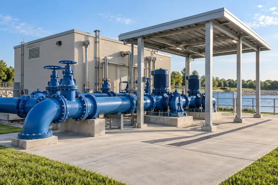
Measurement focus
Local machinery vibration at a defined fixed point
Probe mounting point
Motor bearing housing above the pump structure.
Installation planning
Document the selected direction and distinguish the motor's local reading from whole-pump or foundation movement.
Project brief
Vertical assembly drawing, motor speed, bearing positions and supported measurement band.
Discuss this application

Process cooling-water circulation

Local machinery vibration at a defined fixed point
Dry accessible motor-pump assemblies at an outdoor water pumping installation
Outdoor pumping machinery environment · Illustrative scene

Maintain a vibration trend for circulation pumps that support manufacturing equipment and compare readings at stable process demand.
Measurement focus
Local machinery vibration at a defined fixed point
Probe mounting point
Accessible pump and motor bearing-housing points.
Installation planning
Select rigid housings instead of connected pipework and record operating state when duty pumps change over.
Project brief
Pump type, speed, water temperature and duty/standby strategy.
Discuss this application

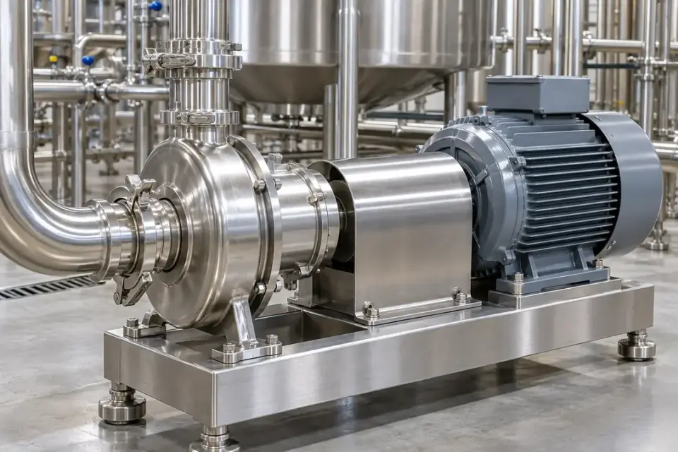
Food and beverage process pumps

Local machinery vibration at a defined fixed point
Stainless-steel sanitary centrifugal pump and external motor drive
Sanitary process-pump environment · Illustrative scene

Observe motor-side or bearing-housing vibration on a sanitary pumping line while keeping the installation outside the product-contact path.

Measurement focus
Local machinery vibration at a defined fixed point
Probe mounting point
Approved fixed drive or bearing housing.
Installation planning
Agree hygienic mounting, washdown exposure and cable cleaning; assess the complete probe-and-connector assembly.
Project brief
Cleaning method, process temperature, mounting approval and pump operating states.
Discuss this application

Chemical transfer pumps in approved areas

Local machinery vibration at a defined fixed point
Dry-mounted centrifugal pump and motor drive showing a fixed machinery measurement region
Dry centrifugal-pump environment · Illustrative scene

Compare vibration changes on compatible pump drives and use the result alongside pressure, flow and maintenance records.
Measurement focus
Local machinery vibration at a defined fixed point
Probe mounting point
Accessible fixed bearing housing outside the fluid path.
Installation planning
Review chemical exposure, temperature and area classification before selecting the probe, terminal and cable.
Project brief
Chemical environment, hazardous-area classification, speed and approved installation point.
Discuss this application
03Fans, ventilation & air systems6 monitoring tasks
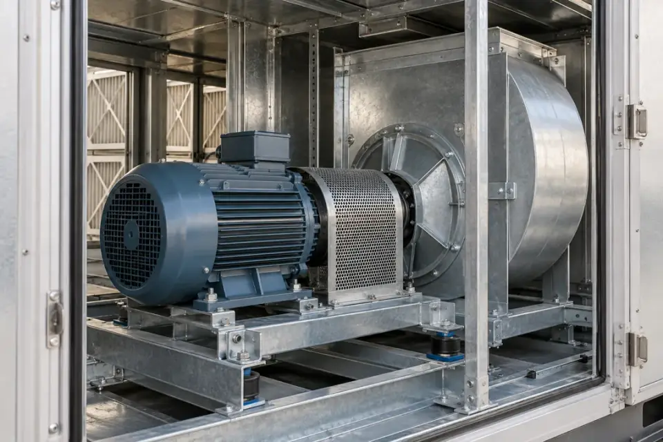
Air-handling fan assembly with accessible fixed motor and fan bearing housings
Air-handling fan machinery · Illustrative scene

Monitor fixed fan-drive and bearing locations rather than blades, flexible ducts or building movement.

Air-handling-unit fan drives

Local machinery vibration at a defined fixed point
Air-handling fan assembly with accessible fixed motor and fan bearing housings
Air-handling fan machinery · Illustrative scene

Follow the vibration of a ventilation fan's drive and bearing arrangement to support inspection of occupied-building services.
Measurement focus
Local machinery vibration at a defined fixed point
Probe mounting point
Fixed motor or fan bearing housing inside the approved service area.
Installation planning
Keep the probe clear of the impeller and belt path; distinguish drive-side measurement from cabinet-panel vibration.
Project brief
Direct or belt drive, fan speed, service access and cable route.
Discuss this application

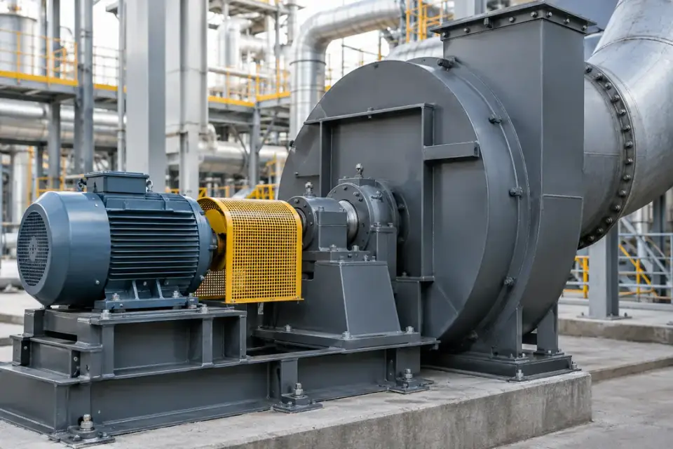
Industrial exhaust fans

Local machinery vibration at a defined fixed point
Industrial centrifugal fan and external drive motor beside its fixed bearing housing
Centrifugal fan drive environment · Illustrative scene

Trend selected fan-bearing points during consistent extraction duty and help maintenance teams identify changes worth inspecting.

Measurement focus
Local machinery vibration at a defined fixed point
Probe mounting point
Stationary fan bearing pedestal or motor bearing housing.
Installation planning
Review contamination and access conditions; mount outside the airflow path on an approved rigid surface.
Project brief
Fan design, RPM, normal duty, dust/chemical exposure and bearing layout.
Discuss this application

Dust-collection fan motors

Local machinery vibration at a defined fixed point
Industrial centrifugal fan and external drive motor beside its fixed bearing housing
Centrifugal fan drive environment · Illustrative scene

Monitor the fixed motor or fan bearings of a dust-extraction system as part of machine-maintenance routines.

Measurement focus
Local machinery vibration at a defined fixed point
Probe mounting point
External bearing housing on the motor or fan drive.
Installation planning
Confirm combustible-dust classification where relevant and keep cabling away from belts and hot or abrasive surfaces.
Project brief
Dust type, area classification, fan-drive layout and expected vibration range.
Discuss this application

Combustion-air fan drives

Local machinery vibration at a defined fixed point
Industrial centrifugal fan and external drive motor beside its fixed bearing housing
Centrifugal fan drive environment · Illustrative scene

Track local vibration at an auxiliary fan drive and compare readings across documented operating demand.

Measurement focus
Local machinery vibration at a defined fixed point
Probe mounting point
Accessible stationary motor or fan bearing housing.
Installation planning
Check the actual surface temperature and cable environment; place the terminal away from excessive radiant heat.
Project brief
Fan speed/load, surface temperature, heat exposure and mounting access.
Discuss this application

Industrial drying-system fans

Local machinery vibration at a defined fixed point
Industrial centrifugal fan and external drive motor beside its fixed bearing housing
Centrifugal fan drive environment · Illustrative scene

Observe fan-drive condition trends that help maintenance teams plan inspections around drying-line production.
Measurement focus
Local machinery vibration at a defined fixed point
Probe mounting point
Fixed drive bearing region outside the heated process chamber.
Installation planning
Review heat, moisture and process contamination; choose a rigid point instead of thin ductwork.
Project brief
Dryer layout, fan duty, temperature at the mounting point and cable path.
Discuss this application

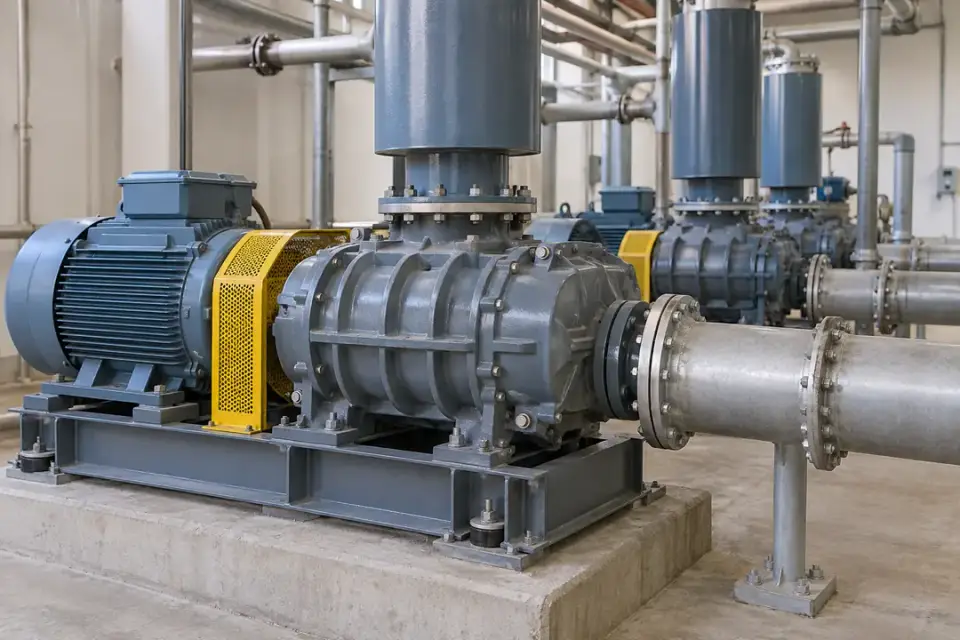
Water-treatment aeration blower drives

Local machinery vibration at a defined fixed point
Water-treatment aeration blower and electric motor with fixed bearing housings
Aeration blower machinery · Illustrative scene

Record repeatable vibration trends at an aeration blower's motor and drive bearings while documenting its process demand.
Measurement focus
Local machinery vibration at a defined fixed point
Probe mounting point
Accessible fixed motor or blower bearing housing.
Installation planning
Separate local drive readings from pipe pulsation and relate comparisons to speed and aeration duty.
Project brief
Blower type, speed, pressure demand, moisture and drive arrangement.
Discuss this application
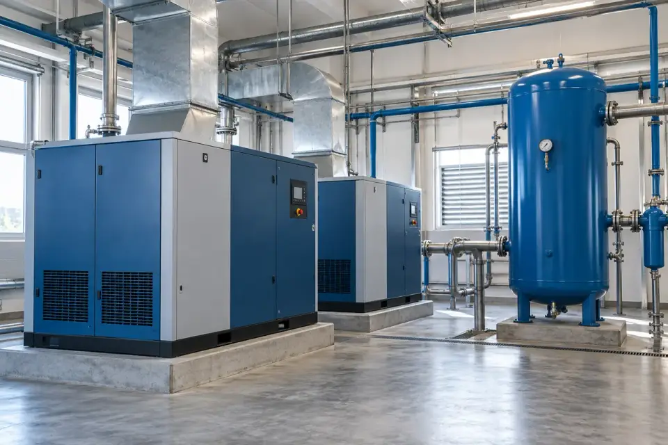
04Compressors & vacuum machinery6 monitoring tasks
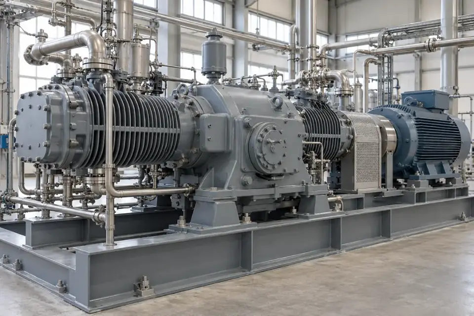
Industrial enclosed air compressor installations in a utility room
Compressed-air equipment environment · Illustrative scene

Keep the measurement point close to a stationary bearing region and match the sensing specification to the compressor duty.

Rotary screw air compressors

Local machinery vibration at a defined fixed point
Industrial enclosed air compressor installations in a utility room
Compressed-air equipment environment · Illustrative scene

Track vibration near the compressor's bearings and compare changes across stable operating and loading states.
Measurement focus
Local machinery vibration at a defined fixed point
Probe mounting point
Approved compressor casing point close to a radial bearing.
Installation planning
Confirm the required frequency band and temperature; avoid assuming that the motor point represents the entire air end.
Project brief
Air-end layout, speed/load range, mounting temperature and required measurement band.
Discuss this application

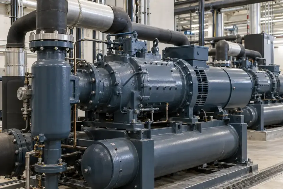
Reciprocating compressor drives

Local machinery vibration at a defined fixed point
Industrial reciprocating compressor with stationary drive and bearing housings
Compressor machinery environment · Illustrative scene

Observe local vibration trends at a drive or bearing region while recording the compressor's normal cyclic duty.
Measurement focus
Local machinery vibration at a defined fixed point
Probe mounting point
Approved fixed drive bearing housing or crankcase point.
Installation planning
Review normal process impulses and amplitude headroom before agreeing a baseline and measurement location.
Project brief
Compressor type, speed, load stages, expected amplitude and safe access.
Discuss this application

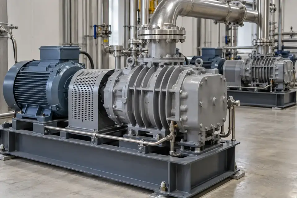
Industrial refrigeration compressors

Local machinery vibration at a defined fixed point
Industrial refrigeration compressor assembly with stationary drive and casing
Industrial refrigeration compressor · Illustrative scene

Follow a compatible compressor drive's vibration trend to support planned inspection of a refrigeration plant.
Measurement focus
Local machinery vibration at a defined fixed point
Probe mounting point
Accessible approved fixed casing or external bearing region.
Installation planning
Review compressor design, surface temperature, refrigerant-area rules and the approved mechanical interface.
Project brief
Compressor configuration, speed, loading steps, temperature and installation approval.
Discuss this application

Rotary-vane vacuum pumps

Local machinery vibration at a defined fixed point
Industrial vacuum pump and fixed electric motor drive in a clean equipment room
Vacuum-pump drive environment · Illustrative scene

Compare local drive and housing vibration during matching vacuum-process states and use changes to guide equipment checks.

Measurement focus
Local machinery vibration at a defined fixed point
Probe mounting point
Approved fixed housing near the rotating assembly's bearing path.
Installation planning
Document the pump's load state and protect the cable from oil, heat and moving service components.
Project brief
Vacuum-pump type, operating speed, process cycle and temperature.
Discuss this application

Dry-screw vacuum systems

Local machinery vibration at a defined fixed point
Industrial vacuum pump and fixed electric motor drive in a clean equipment room
Vacuum-pump drive environment · Illustrative scene

Trend selected stationary measurement points on a dry-screw vacuum system for maintenance review across comparable production cycles.

Measurement focus
Local machinery vibration at a defined fixed point
Probe mounting point
Approved housing point near the monitored bearing region.
Installation planning
Review process contamination and the required frequency band, keeping the radio terminal in a suitable service location.
Project brief
Pump layout, speed/load profile, chemical exposure and desired trend interval.
Discuss this application

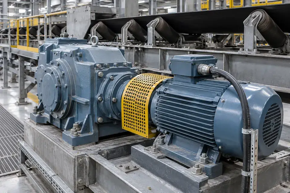
Process-gas compressors in approved areas

Local machinery vibration at a defined fixed point
Industrial reciprocating compressor with stationary drive and bearing housings
Compressor machinery environment · Illustrative scene

Use a qualified installation to observe machinery vibration on a selected process-compressor drive or bearing location.
Measurement focus
Local machinery vibration at a defined fixed point
Probe mounting point
Approved fixed compressor or motor bearing-housing point.
Installation planning
Select the complete assembly against the area's certification and temperature requirements before installation.
Project brief
Gas environment, area classification, machine layout and operating states.
Discuss this application
05Gearboxes, conveyors & intralogistics6 monitoring tasks
Industrial conveyor with a stationary gearbox and electric drive motor
Conveyor gearbox environment · Illustrative scene

Measure the selected drive or bearing path. Operating speed, material load and motion cycles provide context for comparison.

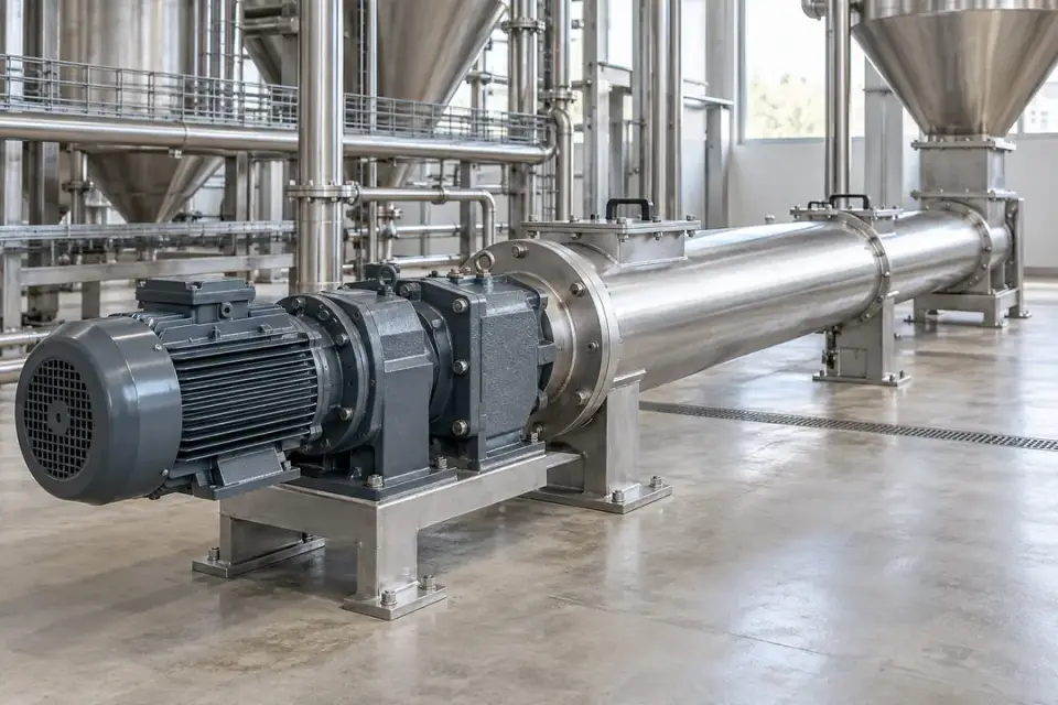
Belt-conveyor drive gearboxes

Local machinery vibration at a defined fixed point
Industrial conveyor with a stationary gearbox and electric drive motor
Conveyor gearbox environment · Illustrative scene

Track local gearbox and motor vibration at a conveyor drive and compare the same transport-duty conditions over time.
Measurement focus
Local machinery vibration at a defined fixed point
Probe mounting point
Fixed gearbox housing near an input or output bearing.
Installation planning
Choose the monitored shaft path and keep the cable clear of pulleys, belts and maintenance openings.
Project brief
Drive layout, gearbox stages, speed range and material-load pattern.
Discuss this application

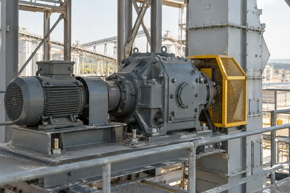
Screw-conveyor gearmotors

Local machinery vibration at a defined fixed point
Industrial screw conveyor with a fixed external geared motor
Screw-conveyor geared drive · Illustrative scene

Observe a screw feeder's external drive vibration to support inspection without placing sensing hardware in the material path.
Measurement focus
Local machinery vibration at a defined fixed point
Probe mounting point
Accessible fixed reducer or motor bearing housing.
Installation planning
Record feed rate and material load, and review dust classification and cable abrasion where relevant.
Project brief
Material type, drive speed, duty cycle and approved external mounting point.
Discuss this application

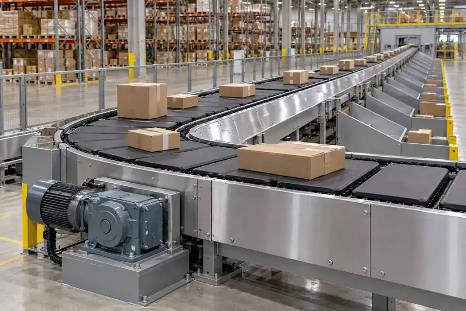
Bucket-elevator drive systems

Local machinery vibration at a defined fixed point
Bucket elevator installation with its external stationary motor and gearbox drive
Bucket-elevator drive environment · Illustrative scene

Maintain a trend at the elevator's drive gearbox or motor bearing region to support accessible machinery inspection.
Measurement focus
Local machinery vibration at a defined fixed point
Probe mounting point
Fixed drive housing at an approved service point.
Installation planning
Separate drive monitoring from tower movement and keep the installation outside the bucket and belt path.
Project brief
Gearmotor arrangement, access platform, speed/load profile and environmental exposure.
Discuss this application

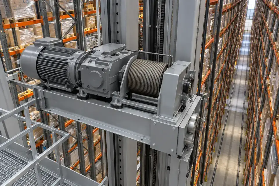
Cross-belt sorter drives

Local machinery vibration at a defined fixed point
Cross-belt sorting line with its stationary external drive and supporting frame
Cross-belt sorting drive environment · Illustrative scene

Observe selected stationary drive bearings and compare vibration within repeatable sorter operating cycles.
Measurement focus
Local machinery vibration at a defined fixed point
Probe mounting point
Approved fixed drive-motor or gearbox housing.
Installation planning
Use a stationary serviceable point; record operating stage and secure the cable outside the sorting mechanism.
Project brief
Sorter layout, drive cycles, speed states and available stationary mounting points.
Discuss this application

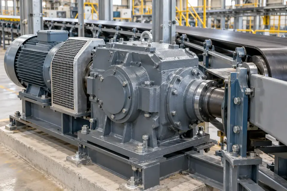
Automated storage and retrieval drives

Local machinery vibration at a defined fixed point
Automated storage and retrieval stacker crane with fixed hoist motor and gearbox
ASRS hoist-drive environment · Illustrative scene

Track a selected hoist or travel drive's machinery vibration while documenting repeatable lift or travel cycles.
Measurement focus
Local machinery vibration at a defined fixed point
Probe mounting point
Approved fixed drive gearbox or motor bearing region.
Installation planning
Review cable management on moving assemblies and interpret drive readings with the same load and motion phase.
Project brief
Machine travel, drive location, cycle stages, cable-management system and payload.
Discuss this application

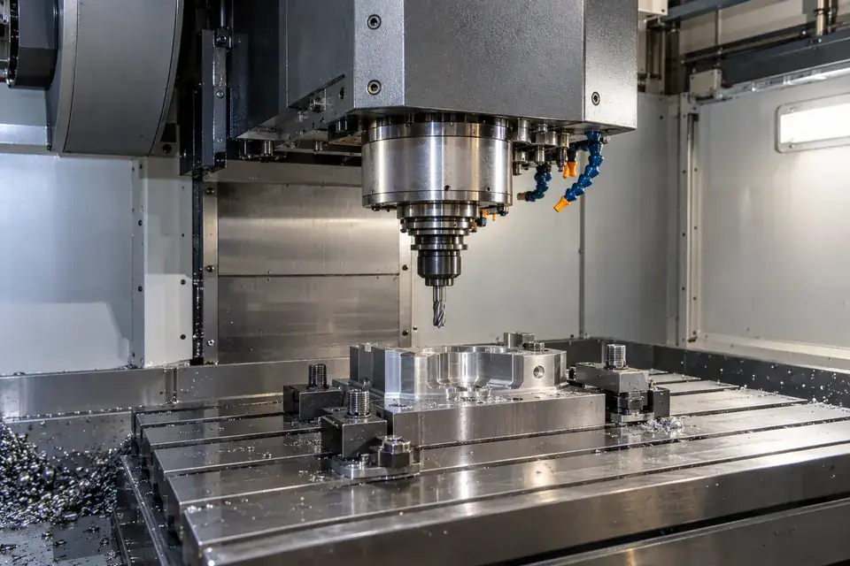
Extruder drive gearboxes

Local machinery vibration at a defined fixed point
Industrial reducer and electric motor on a rigid machinery base
Industrial gearbox environment · Illustrative scene

Compare gearbox vibration under defined process load to support inspection of an extruder's rotating drive components.
Measurement focus
Local machinery vibration at a defined fixed point
Probe mounting point
Fixed gearbox housing close to an identified shaft bearing.
Installation planning
Review multiple gearbox stages, speed and temperature; agree the point rather than treating one reading as the full gearbox condition.
Project brief
Gearbox drawing, process load, speeds, mounting temperature and selected bearing path.
Discuss this application
06Machine tools & metal production6 monitoring tasks
Industrial CNC machine spindle with a fixed spindle housing and guarded machining space
Machine-tool spindle environment · Illustrative scene

Record local machine vibration in the relevant production state, with mounting and cable protection matched to the working environment.

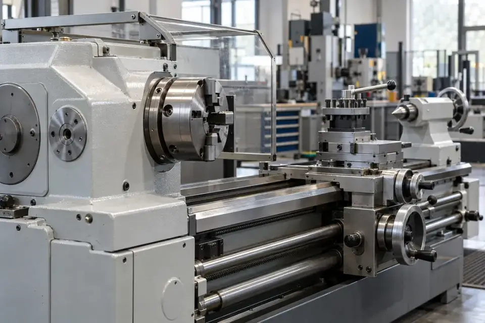
CNC machining-centre spindles

Local machinery vibration at a defined fixed point
Industrial CNC machine spindle with a fixed spindle housing and guarded machining space
Machine-tool spindle environment · Illustrative scene

Follow selected spindle-housing vibration during repeatable machining or run-test conditions to support tooling and machine inspection.
Measurement focus
Local machinery vibration at a defined fixed point
Probe mounting point
Approved stationary spindle housing near a bearing region.
Installation planning
Keep the probe off rotating tooling; review process vibration, coolant, chips and the required measurement bandwidth.
Project brief
Spindle speeds, cutting/run-test stages, amplitude expectations and permitted mounting point.
Discuss this application

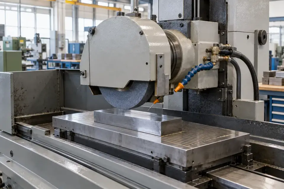
Industrial lathe headstocks

Local machinery vibration at a defined fixed point
Industrial lathe with a stationary headstock housing and guarded machining area
Lathe headstock environment · Illustrative scene

Compare headstock vibration at a repeatable fixed point during matching speed and machining duty.
Measurement focus
Local machinery vibration at a defined fixed point
Probe mounting point
Stationary headstock housing near the monitored spindle bearing.
Installation planning
Keep clear of the chuck and stock; label the sensing direction and document idle or cutting state.
Project brief
Spindle layout, speed range, machining operations and mounting access.
Discuss this application

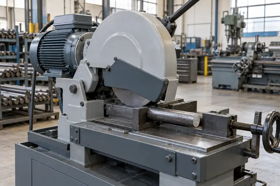
Grinding-machine spindle housings

Local machinery vibration at a defined fixed point
Industrial grinding machine with stationary spindle housing and protective guards
Grinding spindle environment · Illustrative scene

Track local spindle vibration across defined grinding duty and use the history to plan inspection of rotating components.
Measurement focus
Local machinery vibration at a defined fixed point
Probe mounting point
Approved fixed spindle bearing-housing point.
Installation planning
Review abrasive dust, coolant, normal process excitation and amplitude range before selecting the measurement setup.
Project brief
Grinding spindle speed, process cycle, environment and desired metric.
Discuss this application

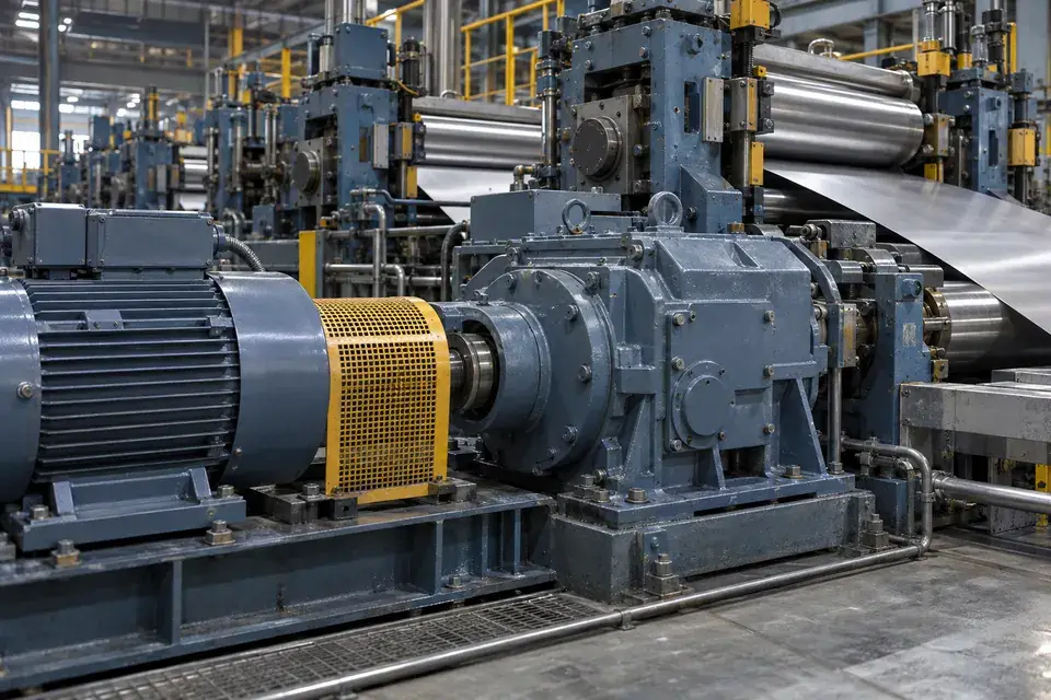
Industrial sawing spindle drives

Local machinery vibration at a defined fixed point
Industrial metal sawing machine with fixed drive housing and protective guards
Industrial sawing drive environment · Illustrative scene

Record vibration at a fixed spindle or drive housing during comparable cutting operations and maintenance run tests.
Measurement focus
Local machinery vibration at a defined fixed point
Probe mounting point
Approved stationary bearing housing outside the blade path.
Installation planning
Protect the cable from swarf and cutting motion; compare the same blade, speed and process stage.
Project brief
Saw configuration, speed, cutting duty, chip exposure and approved mounting location.
Discuss this application

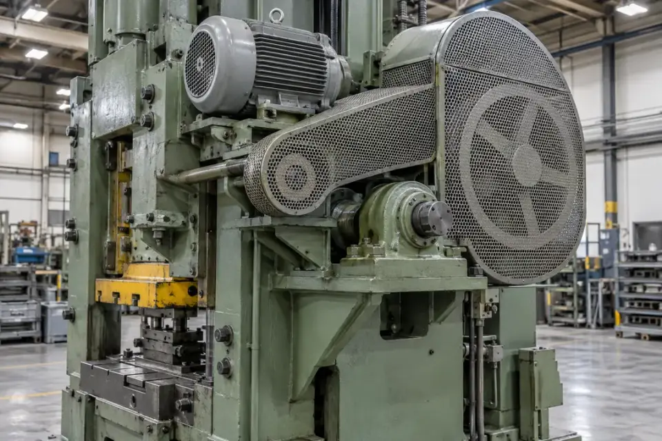
Metal rolling-line drive motors

Local machinery vibration at a defined fixed point
Metal-processing roll equipment with fixed bearing housings and motor drives
Metal-processing drive environment · Illustrative scene

Observe a selected rolling-line motor or reducer bearing path and relate trends to documented production loads.
Measurement focus
Local machinery vibration at a defined fixed point
Probe mounting point
Fixed motor or reducer bearing housing outside the roll path.
Installation planning
Review heat and water spray and select local drive points rather than measuring whole-line or foundation motion.
Project brief
Drive layout, speed/load range, temperature, spray exposure and measurement objective.
Discuss this application

Press drive and flywheel bearings

Local machinery vibration at a defined fixed point
Industrial press with fixed drive bearing supports and guarded flywheel assembly
Industrial press drive environment · Illustrative scene

Track an approved stationary drive-bearing point during repeatable production phases to support routine machinery checks.

Measurement focus
Local machinery vibration at a defined fixed point
Probe mounting point
Fixed drive or flywheel bearing housing outside the moving mechanism.
Installation planning
Assess normal stamping impulses and measurement headroom; keep the installation outside guarded movement and compare the same cycle phase.
Project brief
Press type, cycle stages, expected impulses, selected bearing point and approved access.
Discuss this application
07Process, food, pharmaceutical & paper machinery6 monitoring tasks
Industrial vessel mixer with an external fixed electric motor and gearbox
External mixer drive environment · Illustrative scene

Support production-maintenance routines with local machinery trends, while reviewing process duty, cleanability and mounting access.

Industrial mixer drive assemblies

Local machinery vibration at a defined fixed point
Industrial vessel mixer with an external fixed electric motor and gearbox
External mixer drive environment · Illustrative scene

Observe the motor and reducer's local vibration during matching mixing recipes and batch loads.
Measurement focus
Local machinery vibration at a defined fixed point
Probe mounting point
Approved external fixed drive bearing housing.
Installation planning
Mount outside the vessel and product-contact path and record batch stage, agitator speed and fill level.
Project brief
Mixer configuration, recipes, load stages, cleanability and permitted external mounting point.
Discuss this application

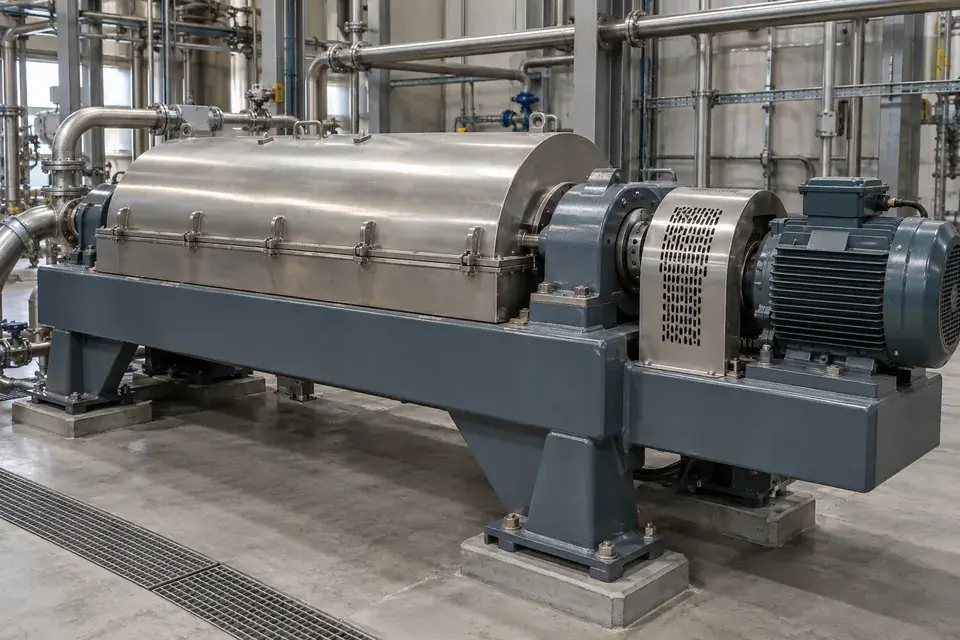
Decanter centrifuge bearing housings

Local machinery vibration at a defined fixed point
Industrial decanter centrifuge with its fixed external bearing housings
Centrifuge machinery environment · Illustrative scene

Trend selected fixed centrifuge bearing points and interpret changes with bowl speed, material feed and operating state.
Measurement focus
Local machinery vibration at a defined fixed point
Probe mounting point
Approved fixed main bearing housing.
Installation planning
Review normal process excitation and multiple vibration sources; select points and data requirements with the machine engineer.
Project brief
Centrifuge layout, speeds, feed states, amplitude range and service access.
Discuss this application

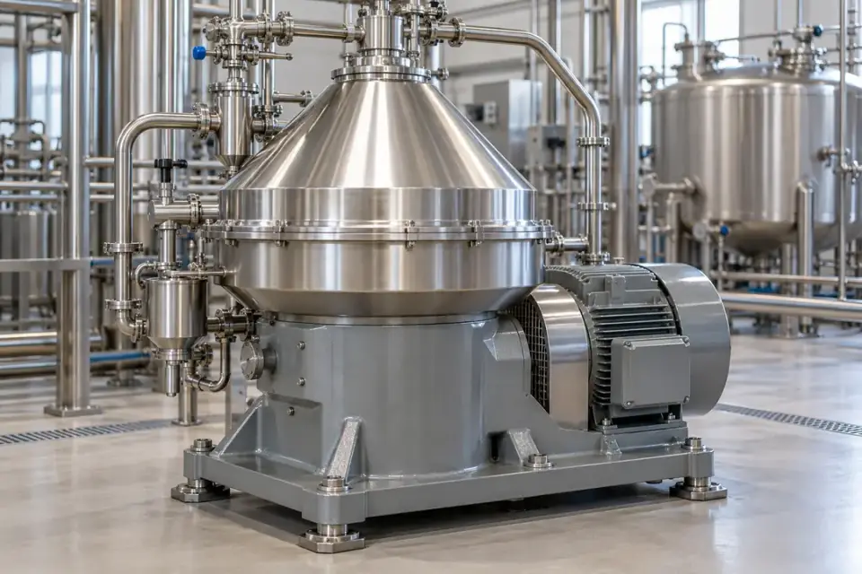
Centrifugal separator drives

Local machinery vibration at a defined fixed point
Vertical centrifugal separator with a stationary external machinery housing
Centrifugal separator environment · Illustrative scene

Observe a separator's approved stationary drive or bearing location to support maintenance review during stable production duty.

Measurement focus
Local machinery vibration at a defined fixed point
Probe mounting point
Fixed bearing housing or approved stationary drive casing.
Installation planning
Keep clear of the rotating bowl and review the required band, operating state and hygienic installation rules.
Project brief
Separator design, speed, process stages, cleaning requirements and bearing layout.
Discuss this application

Filling and capping line drives

Local machinery vibration at a defined fixed point
Automated filling and capping line with accessible external motor drives
Filling and capping line environment · Illustrative scene

Track local motor or gearbox vibration on a production line while comparing repeatable filling and capping duty.
Measurement focus
Local machinery vibration at a defined fixed point
Probe mounting point
Approved fixed motor or reducer housing.
Installation planning
Keep the probe and cable outside packaging/product-contact areas and review washdown and cycle-dependent load.
Project brief
Line speed, drive locations, cycles, cleaning regime and monitoring points.
Discuss this application

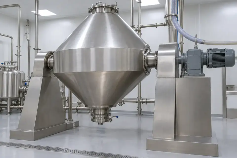
Pharmaceutical vacuum-dryer drives

Local machinery vibration at a defined fixed point
Pharmaceutical vacuum dryer with its external fixed motor and reduction gearbox
Vacuum-dryer external drive · Illustrative scene

Observe an approved external drive point during documented drying stages to support equipment-maintenance records.

Measurement focus
Local machinery vibration at a defined fixed point
Probe mounting point
External fixed motor or reducer bearing housing.
Installation planning
Review cleanroom rules, solvents, temperature and external mounting approval; agree data use with the site's engineering procedure.
Project brief
Dryer arrangement, process stages, area classification and cleanability requirements.
Discuss this application

Paper calender and roll bearings

Local machinery vibration at a defined fixed point
Paper calender rollers supported by fixed service-side bearing housings
Paper calender bearing environment · Illustrative scene

Record local vibration at selected stationary roll-bearing housings and compare equivalent paper-machine production states.
Measurement focus
Local machinery vibration at a defined fixed point
Probe mounting point
Approved fixed roll-bearing housing on the service side.
Installation planning
Review actual surface temperature and moisture and confirm the frequency band for the selected roll speed.
Project brief
Roll speeds, bearing layout, surface temperature, wet exposure and access.
Discuss this application
08Crushing, grinding & heavy processing6 monitoring tasks
Industrial crusher with a stationary shaft bearing housing and drive assembly
Crusher bearing-housing environment · Illustrative scene

Select the rotating drive or fixed bearing housing for machinery monitoring, with range and installation reviewed against normal process excitation.

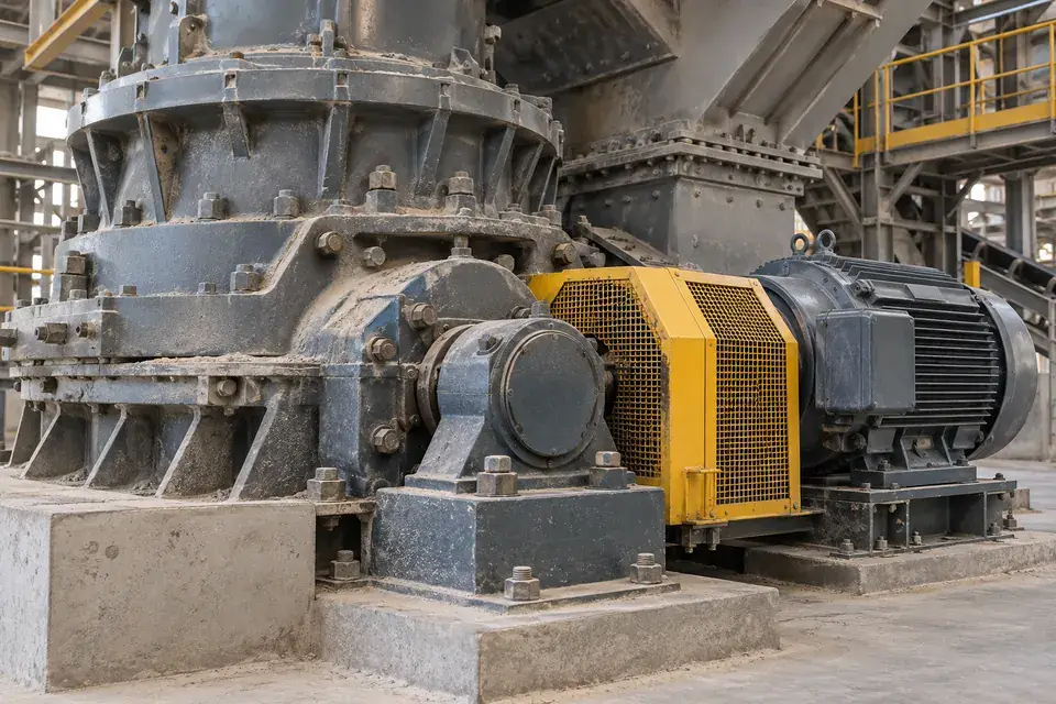
Crusher bearing housings

Local machinery vibration at a defined fixed point
Industrial crusher with a stationary shaft bearing housing and drive assembly
Crusher bearing-housing environment · Illustrative scene

Track a selected crusher bearing or drive point and compare trends against documented feed and operating conditions.

Measurement focus
Local machinery vibration at a defined fixed point
Probe mounting point
Approved fixed shaft-bearing housing or drive motor housing.
Installation planning
Review normal crushing impacts, amplitude headroom, abrasive dust and mechanical cable protection before commissioning.
Project brief
Crusher type, load/feed states, expected amplitude and access to a fixed bearing point.
Discuss this application

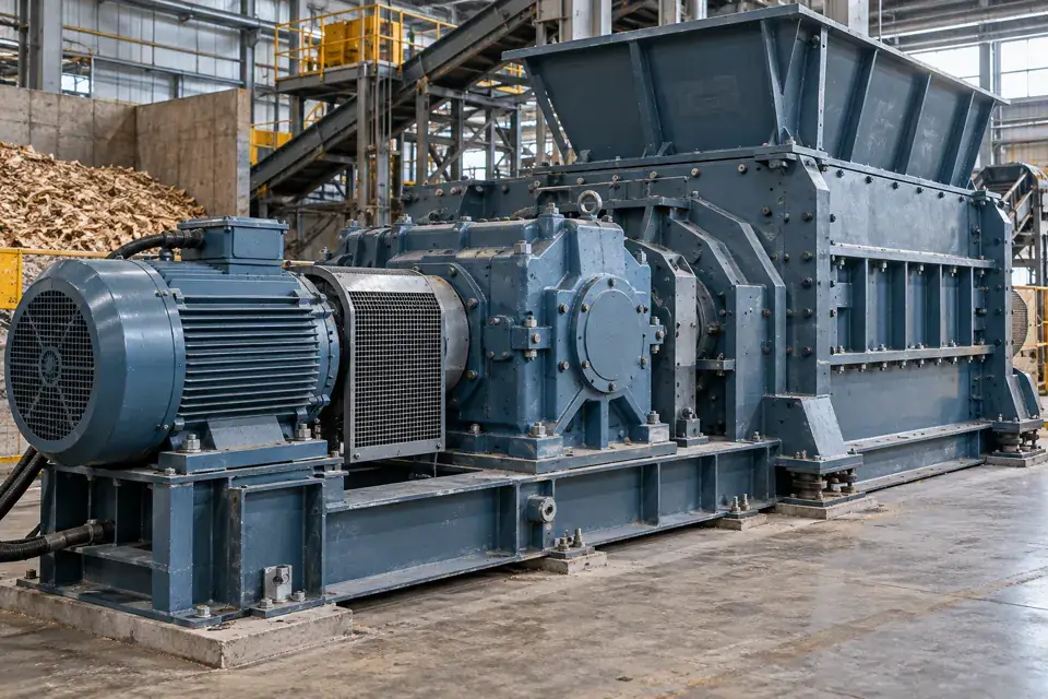
Pulverizer and grinding-mill drives

Local machinery vibration at a defined fixed point
Industrial reducer and electric motor on a rigid machinery base
Industrial gearbox environment · Illustrative scene

Observe local motor or reducer vibration on a grinding line and relate readings to comparable feed and load states.
Measurement focus
Local machinery vibration at a defined fixed point
Probe mounting point
Accessible fixed drive bearing housing.
Installation planning
Identify the drive path, review temperature and dust, and keep cabling clear of rotating couplings and material handling.
Project brief
Mill type, drive speeds, feed conditions, temperature and area classification.
Discuss this application

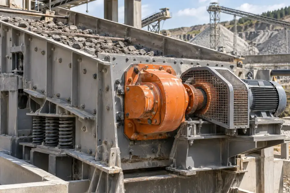
Industrial shredder drives

Local machinery vibration at a defined fixed point
Industrial shredder with fixed external gearbox and electric motor drives
Shredder machinery environment · Illustrative scene

Maintain a vibration history at selected shredder-drive bearings while recording the material and normal operating cycle.
Measurement focus
Local machinery vibration at a defined fixed point
Probe mounting point
Approved fixed drive motor or reducer housing.
Installation planning
Review process impacts and headroom, and protect the probe cable from debris and moving maintenance components.
Project brief
Shredder design, materials, load cycle, expected impacts and bearing access.
Discuss this application

Vibrating-screen exciter bearings

Local machinery vibration at a defined fixed point
Industrial vibrating screen with local exciter shaft bearing housings
Screen exciter bearing environment · Illustrative scene

Observe local rotating-exciter bearing vibration as a machinery trend at a defined stationary housing point.

Measurement focus
Local machinery vibration at a defined fixed point
Probe mounting point
Approved exciter or drive bearing housing.
Installation planning
Confirm band and amplitude for the selected bearing objective; the installation concerns local machinery rather than screen-body movement.
Project brief
Exciter layout, normal excitation, bearing point, range and required measurement band.
Discuss this application

Cement-mill motor and gearbox bearings

Local machinery vibration at a defined fixed point
Industrial reducer and electric motor on a rigid machinery base
Industrial gearbox environment · Illustrative scene

Track a selected mill-drive bearing path and use consistent production-load records to make trend comparisons useful.

Measurement focus
Local machinery vibration at a defined fixed point
Probe mounting point
Approved fixed motor or gearbox bearing-housing point.
Installation planning
Review multiple gear stages and normal process excitation, plus dust, heat and approved maintenance access.
Project brief
Drive drawing, speeds, load states, heat/dust exposure and selected bearing path.
Discuss this application

Wood-chipper drive bearings

Local machinery vibration at a defined fixed point
Industrial shredder with fixed external gearbox and electric motor drives
Shredder machinery environment · Illustrative scene

Observe a fixed drive or rotor-bearing housing and compare the vibration history within documented material-processing duty.

Measurement focus
Local machinery vibration at a defined fixed point
Probe mounting point
Approved stationary drive or rotor-bearing housing.
Installation planning
Review normal cutting impulses and range, protecting cables from chips and keeping the probe outside the rotor guard.
Project brief
Chipper design, rotor speed, feed conditions, expected impulses and service point.
Discuss this application

SERIES & CONFIGURATIONS

One product family.
A configuration for your machine.

H200, H300 and H500 are published H Series family identifiers. Specify the complete probe, terminal, wireless variant and operating profile in the configuration proposal for your project.

H Series high-frequency vibration sensors — configuration specifications
Published family modelsH200 / H300 / H500
Vibration velocity RMS range0–50 mm/s
Measurement frequency range10–5,000 Hz
Measurement axesSingle-axis or triaxial, by selected configuration
Vibration velocity RMS display resolution0.1 mm/s
Published accuracy condition±1% at 80 Hz calibration; confirm the full supplied measurement specification
Sensing arrangementCabled external probe at a rigid motor bearing-housing or machine measurement point
Wireless variants4G / NB-IoT / LoRa, by supplied model and regional configuration
Data integrationMQTT listed; confirm the complete path for the supplied variant
Terminal enclosure ratingIP68; specify probe, cable and connector suitability separately
Published operating temperature−20°C to +70°C; confirm component-specific limits for the installation
Published storage temperature−20°C to +80°C
Device configurationNFC activation / local setup; OTA updates, by supplied configuration
Battery-life referenceOver 10 years at one-hour reporting under specified conditions; configuration and duty dependent

Bring the specification back to your project.

01

Define the machine point

Share the component, rigid mounting surface, measurement direction, speed range and normal load states.

02

Specify the measurement

Select single-axis or triaxial sensing and specify the machine frequencies of interest within the 10–5,000 Hz measurement range. The vibration velocity RMS range is 0–50 mm/s with a display resolution of 0.1 mm/s. Agree acquisition duty, reporting and calibration requirements.

03

Plan the full deployment

Review probe and cable conditions, terminal location, radio coverage, reporting, alerts and the platform handover.

CONNECTIVITY & INTEGRATION

Your machine.
Your data destination.

Connect configured readings to Hitelecom Cloud or a compatible customer platform. MQTT is listed in the family specification. Agree the message format, endpoint and supported authentication with the selected radio variant and onward connection.

4G / NB-IoT

For distributed locations

Vibration terminalMobile networkYour platform

Select the supplied modem and regional bands around operator availability and coverage at the terminal position. Agree the measurement schedule, reporting profile and configured notification workflow.

  • Installation country and operator
  • Signal at the actual mounting position
  • Measurement schedule, reporting and alert workflow
LoRa

For points across one site

Vibration terminalsReceiver / gatewayYour platform

Match the supplied radio protocol, regional settings and receiver or gateway. Specify any LoRaWAN requirement with the model and complete onward connection.

  • Supplied radio protocol and gateway compatibility
  • Site layout and radio coverage
  • Gateway power and onward data connection

Make the first reading useful.

Agree device identity, machine and mounting-point labels, measurement quantity, units and timestamps in a sample message. Confirm the MQTT endpoint and supported authentication for the supplied configuration, then test the complete path to the intended platform and notification recipients.

Discuss platform integration ↗

ANSWERS FOR YOUR PROJECT

Frequently
asked questions.

Answers for specifying machinery measurement, planning the cabled probe installation and connecting readings to the maintenance workflow.

Ask about your project ↗
What does the Hitelecom machinery vibration sensor measure?

The Hitelecom H Series uses a cabled external probe for high-frequency machinery vibration monitoring. Vibration velocity is reported as a root mean square (RMS) value over a 0–50 mm/s range, with a display resolution of 0.1 mm/s. The specified measurement frequency range is 10–5,000 Hz. Select single-axis or triaxial sensing for the machine and mounting point, then configure the wireless reporting profile.

Where should a vibration probe be mounted on an electric motor?

Mount the probe directly on an approved rigid part of the motor bearing housing or end shield, close to the bearing being monitored. Use the supplied mounting method and a prepared measurement surface. Record the point identifier and the single-axis direction or triaxial orientation. Secure the cable and locate the wireless terminal separately for access and radio coverage.

Which industrial machines are suitable for this monitoring approach?

Common project candidates include electric motors, pumps, fans, compressors, gearboxes, conveyors, machine-tool spindles, mixers and centrifuges. Select a rigid, stationary measurement point near the component of interest, and match the supplied probe’s usable frequency band, range and installation conditions to the machine. This external-probe family is intended for high-frequency machinery vibration monitoring.

How does a wired probe work with a wireless monitoring terminal?

The probe cable connects the mechanical measurement point to the monitoring terminal. The configured 4G, NB-IoT or LoRa connection handles the remote data link. Plan the probe position, approved cable length and terminal location together, considering machine access, cable protection and radio coverage.

What is the vibration measurement frequency range?

The specified measurement frequency range is 10–5,000 Hz. This is the vibration frequency range measured at the probe, rather than a wireless reporting rate. The 80 Hz calibration condition is a separate calibration reference. Share the machine speed, target components and mounting arrangement so the acquisition and reporting profile can be matched to the application.

Does the sensor support single-axis or triaxial vibration measurement?

Yes. Single-axis and triaxial configurations are available. A single-axis configuration measures vibration along its selected sensing direction. A triaxial configuration measures along three axes at the same mounting point. Specify the configuration and mounting orientation for your machine; the vibration velocity RMS display resolution is 0.1 mm/s.

How should readings be compared on variable-speed or cyclic machines?

Record the machine's speed, load and operating stage with the monitoring plan. Establish comparable baselines for the states that matter, such as a stable running speed or a repeatable production-cycle phase. Review changes against those conditions and the maintenance history so the trend supports a focused inspection.

What helps preserve a useful high-frequency measurement?

Use the approved mounting method on a clean, flat, rigid measurement surface. Mechanical coupling affects the mounted frequency response, so the sensor interface and any mounting base should be reviewed for the target band. Secure the cable with strain relief and suitable slack, and route it safely around moving parts and motor-power wiring.

How can vibration trends support the maintenance workflow?

Agree a normal operating baseline, the values to review and a practical inspection response. A sustained change at a labelled measurement point can help the team prioritise checks and compare readings before and after maintenance. Detailed fault interpretation depends on the machine, the available measurement data and the analysis method used in the project.

What information helps Hitelecom prepare a suitable configuration?

Share the machine type, speed range, operating cycle, target components, photos of the proposed mounting points and whether you need single-axis or triaxial measurement. Include the environment, cable-route requirements, measurement/reporting intervals, country and preferred platform or communications link. These details help align the probe, terminal and data requirements with your installation.

LET'S TALK ABOUT YOUR PROJECT

Tell us about
your machine.

Share the machine, operating conditions and monitoring objective. We’ll help match the cabled probe, measurement configuration and wireless connection, then discuss your quotation.

sales@hitelecom.cn ↗

Start with a machine and a mounting point.

A machine photo, bearing-housing detail or maintenance specification helps us plan the installation. Add operating speed, load, cable routing and your reporting or platform requirements.

PROJECT ENQUIRY

Let’s find your configuration.

High-frequency machinery vibration monitoring

Review your brief, then send it with your email app.

You can also email your project details directly.