


Wireless water leak sensor.The water event. The next step.

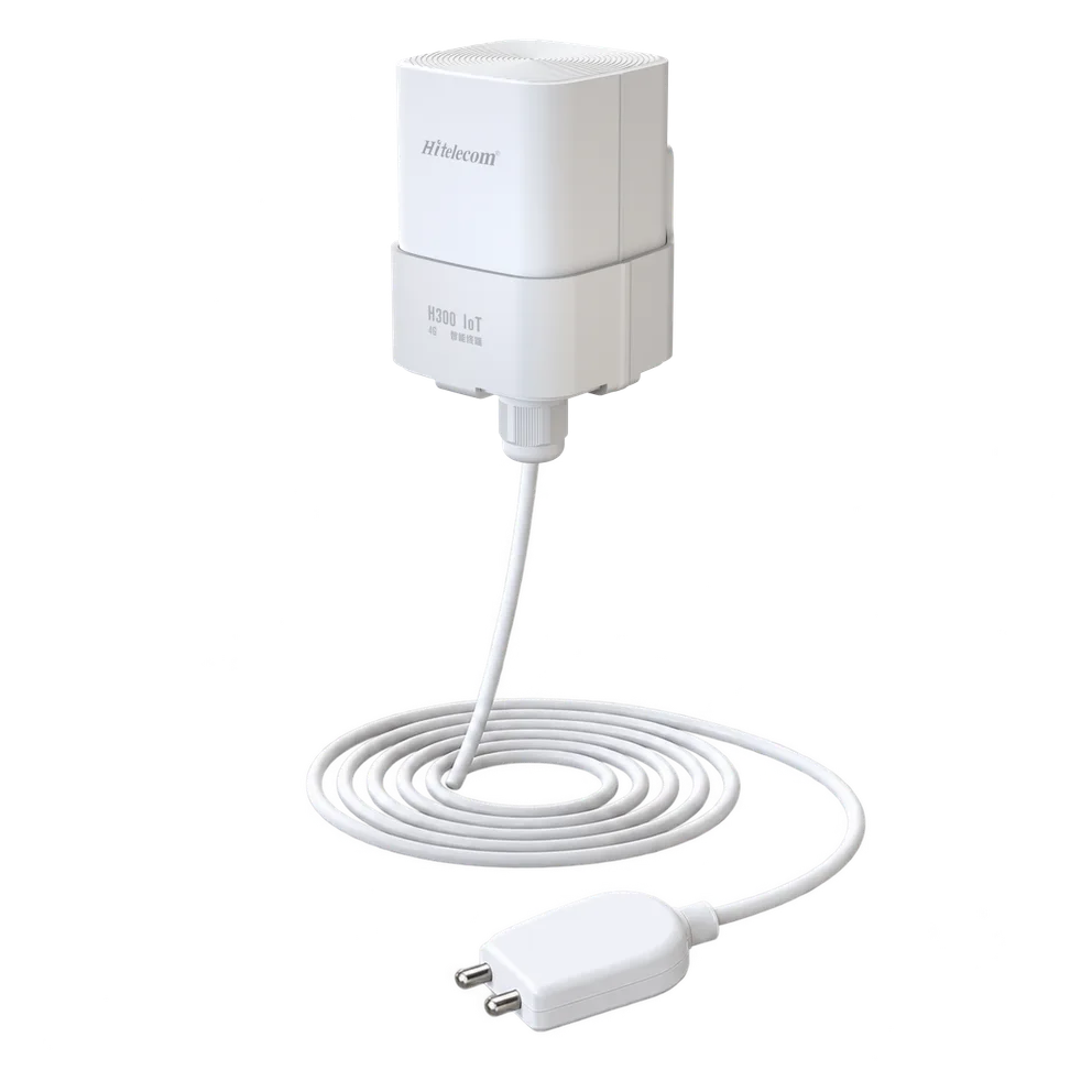
Hitelecom H300 wireless water leak sensor with a cable and a two-pin water-detection probe
H300 · Water leak sensor with two-pin probe

The Hitelecom H Series wireless water leakage sensor monitors for water reaching selected sensing locations around industrial equipment, utilities and critical spaces. Choose H200 for LoRa, H300 for 4G or H500 for NB-IoT; H300-WL002A is the specified 4G model. Match the sensing arrangement to the water source, expected flow path and installation, then define how events reach the receiving platform and the responsible team.

4G water-leak modelH300-WL002AH200 LoRa · H500 NB-IoT alternatives
Water presence at selected locationsDefined sensing pointsPlan the sensing arrangement for the site
Events, recipients and next stepsYour response pathAgree the platform and notification workflow

KEY FEATURES

A local water event.
A clear operational response.

Bring sensing locations, wireless coverage and the maintenance workflow into one installation plan.

Water-presence monitoring

Observe water reaching selected sensing locations near equipment, services and vulnerable assets.

Three wireless families

H200 uses LoRa, H300 uses 4G and H500 uses NB-IoT. Select the connection around site coverage and infrastructure.

H300-WL002A

A specified 4G model within the H Series water-leak family. Confirm the complete sensing and installation configuration for your project.

Installation-led coverage

Use likely leak sources and the path water follows to plan the sensing locations and required coverage.

Liquid-specific selection

Identify the water or condensate involved and any additives, contamination or cleaning conditions before choosing the sensing assembly.

A defined notification path

Agree event handling, responsible recipients and acknowledgement through the receiving monitoring system.

Industrial application planning

Build point layouts around pumps, cooling water, equipment trays, service routes and designated low points.

A serviceable installation

Plan access for inspection, controlled testing, cleaning and recovery checks throughout the operating period.

PLAN THE WATER-DETECTION POINT

Start with the source.
Follow the water path.

A leak detector becomes useful when water can reach its sensing element and the event reaches the right team. Define the liquid, route and operational response before choosing the installation.

01

A known collection point

For drip trays, pump bases and designated low spots. Place the sensing element where the assessed leak path collects water, with access to inspect and test it.

Define the detection layout
Leak source · Tray or floor layout · Drainage · Sensing position
Discuss this layout ↗
02

Multiple collection points

For an equipment row, map the collection points identified by the site survey. Confirm the required number of point-sensing devices and the installation layout.

Define the detection layout
Collection points · Site layout · Number of devices · Service access
Discuss this layout ↗
03

A water event and a response

Define the reported condition, how it is transmitted and who should act. Agree detection behaviour, notification timing and recovery handling as separate parts of the project.

Define the detection layout
Event state · Wireless route · Recipients · Timing · Recovery
Discuss this layout ↗
DETECTION & INSTALLATION

Position the sensing element. Keep the complete installation accessible.

Trace possible releases from joints, seals, hoses, drains or collection trays to the proposed sensing position. Review floor slope, barriers, normal washdown and cleaning practices. Match the sensing assembly to the actual liquid and operating conditions; locate the transmitter and its connections within their approved conditions. Keep routes clear of damage and leave practical access for inspection. Use a controlled wet test and recovery check to verify each installed point and its complete notification path.

FROM WATER DETECTION TO SITE ACTION

Recognise the event.
Give your team a next step.

Agree what happens between water contacting the sensing element and a responsible person receiving an actionable event. Detection behaviour, wireless reporting, platform rules and recovery handling each contribute to the result. Commission the complete path under the network conditions at the actual mounting position.

01

Detect

The supplied sensing assembly responds to water reaching its monitored location. Verify the actual liquid and sensing position during commissioning.

02

Deliver

The selected H200, H300 or H500 connection carries the configured event to the agreed receiving system. Check message identity, time and connection behaviour.

03

Respond

The receiving workflow directs the event to the responsible team. Define acknowledgement, inspection, escalation and the check that returns the point to service.

COMMISSION THE COMPLETE PATHTest the event. Check the recovery.

Use the supplied instructions to test a controlled water event, the received message, the intended notification and any supported recovery indication. Record the measured end-to-end timing for the site. If a local warning or equipment action is required, include its interface and behaviour in the engineering scope and test it separately.

APPLICATIONS

Industrial water-leak monitoring.
Across equipment and critical spaces.

Explore eight industrial groups and 40 defined monitoring contexts, from machine cooling and pump rooms to electrical facilities, data centres, storage and below-grade services. Each task identifies the water source, useful sensing position and project conditions.

8 industry categories 40 monitoring tasks

Images illustrate representative environments. Final sensing positions and liquid suitability are selected for the supplied configuration and site layout.

01Factory production equipment5 monitoring tasks
Complete CNC machining centre with its enclosure, control console, cooling-service unit and surrounding factory floor
Complete machining centre and cooling-service area

Put water detection beside the connections that move, wear or get serviced: cooling circuits, flexible hoses, valves and equipment service bays. Match each sensing point to a practical inspection route.

Machine-tool cooling connections

Local presence of water or a confirmed compatible water-based coolant.
Complete CNC machining centre with its enclosure, control console, cooling-service unit and surrounding factory floor
Complete machining centre and cooling-service area

Machine tools may have spindle cooling, water supply and water-based coolant circuits close to moving hoses and service connections. Place detection at a defined collection point outside the machining enclosure to identify unexpected liquid reaching that position. For coolant mixtures, confirm the actual formulation, contamination and sensing compatibility before selecting the configuration and arranging a representative site test.

What to detect
Local presence of water or a confirmed compatible water-based coolant.
Detection point
External cooling hose connections, service trays and floor collection points beside the machine.
Installation approach
Agree a mounting point clear of moving axes, hot surfaces and routine spray. Route and secure the sensing assembly so machine servicing remains practical, and validate detection with the actual approved fluid.
Specify for your project
Share the machine type, circuit fluid, likely collection point and routine cleaning method.
Discuss this application

Injection-moulding cooling manifolds

Water reaching the selected cooling-manifold collection area.
Injection-moulding machine in a clean industrial production hall
Injection-moulding production environment

Mould cooling systems contain multiple supply and return connections that are disconnected or adjusted during tool changes. A defined detection position beneath an external manifold or hose service area can help the maintenance team investigate water that escapes during production. Separate normal tool-change drainage from unexpected wetness, and associate the alert with the machine and cooling zone concerned.

What to detect
Water reaching the selected cooling-manifold collection area.
Detection point
External mould-cooling manifolds, hose connection banks and approved drip-tray low points.
Installation approach
Position the approved sensing assembly outside the mould movement area and clear of hot tooling. Keep connection access available, protect exposed routing and test the chosen point under normal production and tool-change conditions.
Specify for your project
Tell us the manifold layout, tool-change drainage routine and number of machines or cooling zones.
Discuss this application

Resistance-welding cooling stations

Water present at the selected external welding-cooling service point.
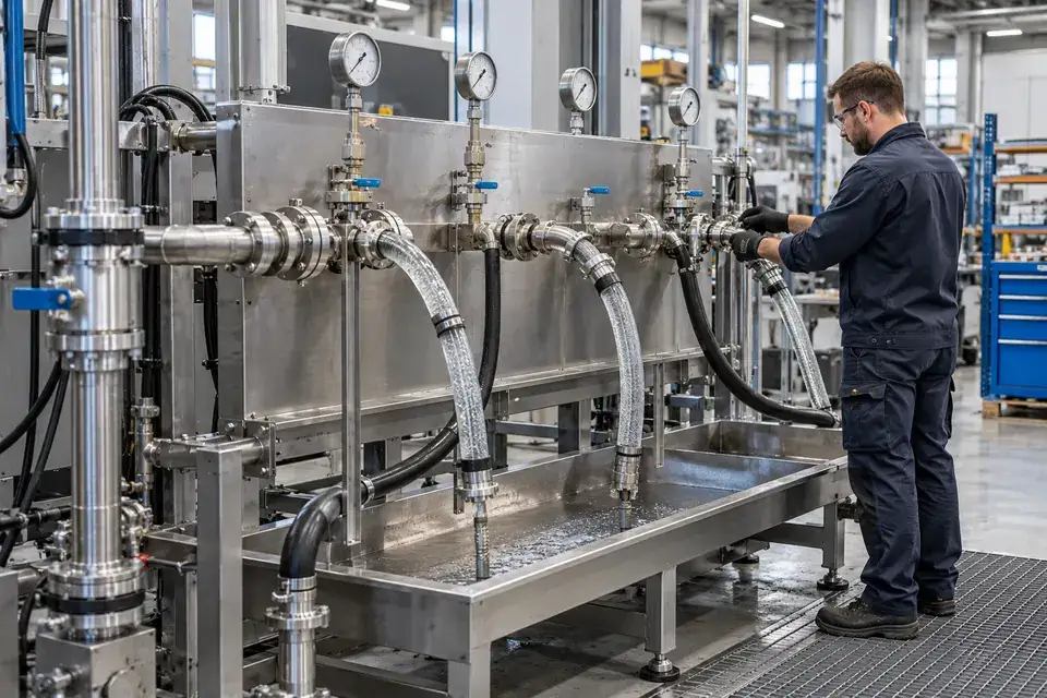
An external cooling-water manifold beside a guarded industrial welding cell
Welding-cell cooling-service environment

Water-cooled resistance-welding equipment can have flexible cooling connections between a utility supply, controller and welding cell. Detection at an accessible service-side collection point can identify water escaping beyond the intended circuit. Link each point to the affected welding station and its maintenance team so staff can inspect the relevant cooling connection.
What to detect
Water present at the selected external welding-cooling service point.
Detection point
Cooling hose junctions, external distribution blocks and service-side collection trays.
Installation approach
Choose an approved location outside robot travel, welding spatter and electrical access zones. Secure the assembly against maintenance impacts and confirm the sensing point remains reachable without entering the operating cell.
Specify for your project
Provide the welding-cell cooling layout, safe service boundary and expected inspection response.
Discuss this application

Water-circuit production test rigs

Water reaching an agreed test-rig tray or floor detection point.
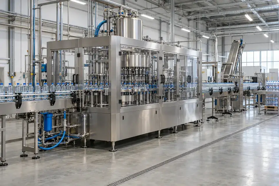
Industrial water-circuit test manifold with flexible connections and a shallow collection tray
Water-circuit test-rig environment

End-of-line test rigs may connect products repeatedly to water-filled fixtures, manifolds or quick couplings. A sensor at a defined tray or external collection point can flag water that remains outside the intended test circuit. Use the test sequence to distinguish expected draining from water that requires inspection, and identify the fixture or station in the notification.
What to detect
Water reaching an agreed test-rig tray or floor detection point.
Detection point
External fixture connections, coupling service trays and test-station collection points.
Installation approach
Select a point away from moving fixtures and intentional discharge. Make the sensing assembly accessible for cleaning, and agree how wet and dry phases of the test cycle affect notification handling.
Specify for your project
Share the test fluid, cycle stages, intended drainage path and station identification scheme.
Discuss this application

Packaging-line water service bays

Local water presence at a selected packaging-equipment service point.
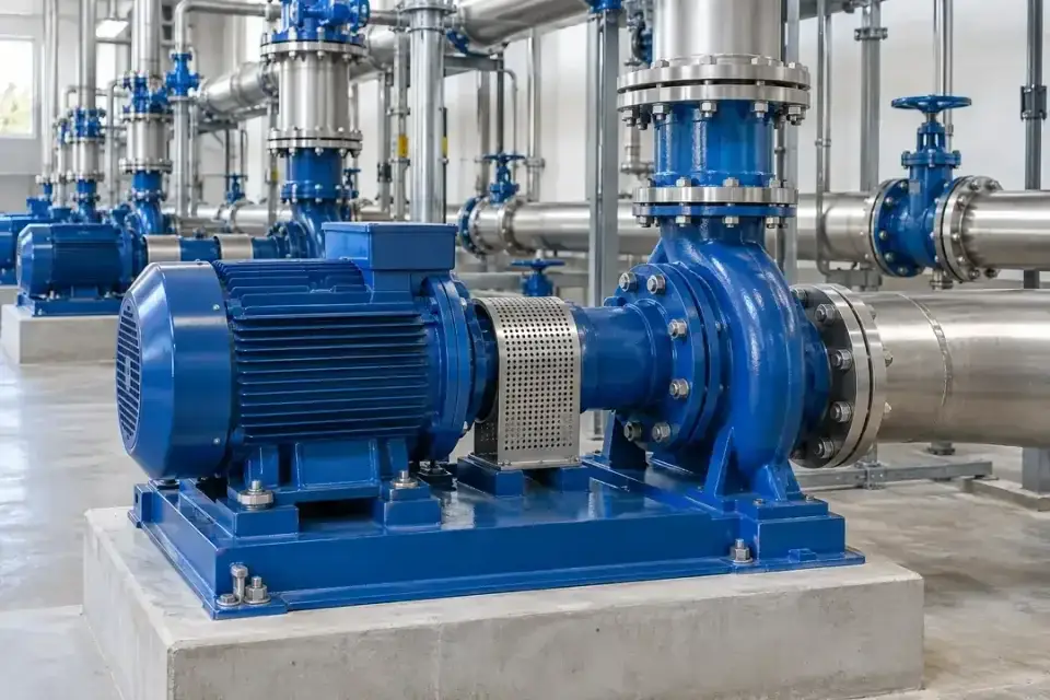
Enclosed bottle-filling and capping installation with conveyors, service connections, machine bases and a clear factory aisle
Complete filling and packaging-line installation

Packaging and converting lines can include water-cooled tooling, rinsing services or local water conditioning equipment beside conveyors and electrical controls. Detection at an external service bay gives the maintenance team a named location to inspect when water reaches the monitoring point. Map the sensing point to the relevant machine section and distinguish production washdown from leakage that requires maintenance attention.
What to detect
Local water presence at a selected packaging-equipment service point.
Detection point
Water-service connection bays, cooling skid bases and approved collection trays beside the line.
Installation approach
Keep the detection assembly clear of conveyors, cleaning machinery and pedestrian routes. Agree a service-side mounting position, then validate the installation against both production conditions and the site's washdown routine.
Specify for your project
Describe the line's water services, washdown schedule and machine sections requiring individual identification.
Discuss this application
02Plant utilities and water services5 monitoring tasks
Blue industrial booster pumps and connected water pipework in a utility room
Water booster-pump environment

Follow water from treatment and distribution to cooling, heating and condensate collection. Local detection helps maintenance teams identify which utility area needs inspection when water reaches an unexpected position.

Water pump and booster skids

Water presence at a selected pump-skid base or drainage collection point.
Blue industrial booster pumps and connected water pipework in a utility room
Water booster-pump environment

Pump seals, flange joints, valves and flexible connectors create several possible water-release points around a booster or transfer skid. Choose detection positions using the skid's drainage pattern rather than the pump count alone. An alert can direct the maintenance team to inspect the named skid or collection area and check the relevant seal, joint or valve.
What to detect
Water presence at a selected pump-skid base or drainage collection point.
Detection point
Skid trays, seal-area drainage routes and low points near water-pipe flange connections.
Installation approach
Place the approved sensing assembly where a small release can reach it without blocking drainage. Keep it clear of rotating equipment, service lifting paths and areas routinely wet during pump maintenance.
Specify for your project
Send the pump-skid layout, drainage direction and whether individual pumps or the whole skid need identification.
Discuss this application

Chillers and heat-exchanger stations

Local water or confirmed compatible cooling-fluid presence at an external collection point.
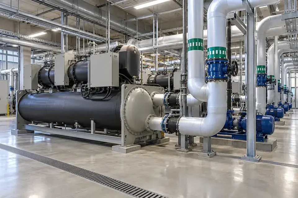
Industrial chiller with insulated water pipework and adjacent plant services
Industrial chiller environment

Cooling-water stations combine pipe joints, strainers, valves and heat-exchanger connections within a limited service area. Local water detection can identify wetness at the selected skid or floor position and help staff inspect the relevant circuit. Distinguish cooling-water leakage from normal condensate, and confirm compatibility where glycol, treatment chemicals or another water-based mixture is present in the monitored circuit.
What to detect
Local water or confirmed compatible cooling-fluid presence at an external collection point.
Detection point
Cooling-water valve stations, exchanger connection trays and chiller service-side low points.
Installation approach
Locate the approved sensing element outside hot or cold surfaces that exceed its specified conditions. Keep insulation and drain access intact, and test the actual fluid and collection route before handover.
Specify for your project
Specify the cooling-fluid mixture, connection temperatures and whether condensate is normally present.
Discuss this application

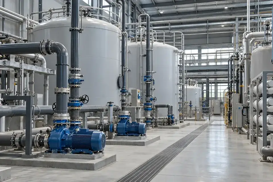
RO and water-softening systems

Water presence at an agreed treatment-skid collection point, using a compatible sensing method.
Factory water-treatment vessels, a circulation pump and service pipework
Factory water-treatment environment

Reverse-osmosis and softening skids contain service connections that are opened during filter replacement, membrane work or valve maintenance. Place the probe outside the normal drain path to detect water reaching an unintended tray or floor area. For low-conductivity permeate, confirm the sensing method with a representative sample rather than assuming every water-detection configuration performs identically.
What to detect
Water presence at an agreed treatment-skid collection point, using a compatible sensing method.
Detection point
External filter housings, membrane connection bays and skid-base collection trays.
Installation approach
Agree detection positions around the normal drain route and service clearances. Confirm the expected water conductivity, temperature and cleaning conditions, then validate response with samples from the actual monitored circuit.
Specify for your project
Tell us whether the monitored stream is feed water, softened water, permeate or another treatment stream.
Discuss this application

Boiler makeup-water service areas

Water presence at a suitably tempered makeup-water collection point.
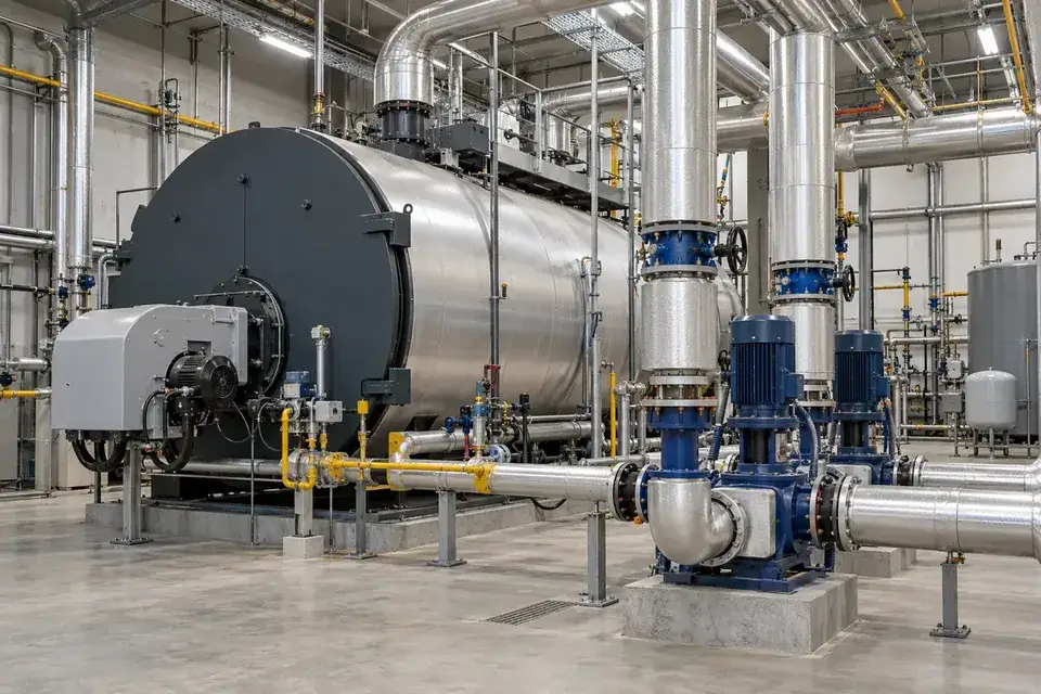
Industrial boiler house with circulation pumps and insulated water services
Boiler-house water-service environment

Boiler installations often have makeup-water treatment, supply valves and external service pipework around the main plant. Water detection can be specified for an accessible, suitably tempered collection position within these auxiliary areas. Identify the source circuit and expected temperature before selection, and keep boiler pressure protection, steam control and other plant safeguards under their dedicated equipment and operating procedures.
What to detect
Water presence at a suitably tempered makeup-water collection point.
Detection point
Makeup-water valve areas, auxiliary treatment-skid bases and approved external drainage interfaces.
Installation approach
Use an approved collection point clear of steam releases and hot surfaces. Verify the temperature that can reach the sensor, preserve plant access and confirm compatibility with the actual makeup-water treatment.
Specify for your project
Provide the makeup-water layout, potential release temperature and the proposed safe collection point.
Discuss this application

Compressor condensate collection

Compatible water-based condensate reaching an unintended external collection position.
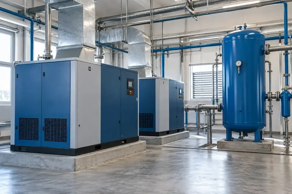
Industrial compressed-air room with compressors and an upright receiver vessel
Compressed-air utility environment

Compressed-air systems collect condensate through drains, separators and treatment units. Detection outside the intended collection path can help identify an overflowing receiver tray or disconnected drain route that needs inspection. Confirm the condensate composition and sensing compatibility, especially where oil carryover or treatment residues may occur, and distinguish this local wetness task from monitoring the compressed-air system itself.
What to detect
Compatible water-based condensate reaching an unintended external collection position.
Detection point
Condensate treatment unit bases, drain receiver trays and external hose collection points.
Installation approach
Choose an accessible position away from pressurised air outlets and moving equipment. Assess the actual condensate before selection, keep disposal routes clear and include inspection and cleaning in the maintenance routine.
Specify for your project
Share the compressor type, condensate treatment arrangement and known oil or chemical content.
Discuss this application
03Electrical and energy facilities5 monitoring tasks
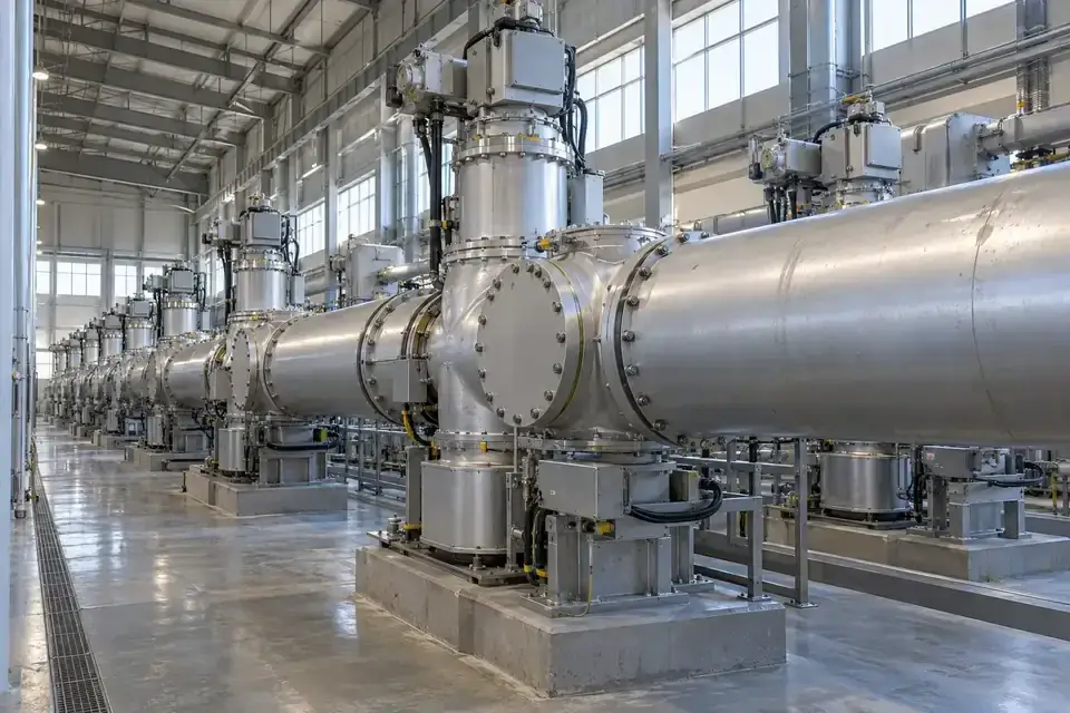
Enclosed gas-insulated switchgear in a spacious electrical equipment hall
Enclosed switchgear-hall environment

Monitor suitable floor and drainage interfaces around electrical rooms. Place sensing equipment where it can be installed and maintained safely, with the detection area and response agreed by the facility team.

Switchgear-room water ingress

Water reaching a selected switchgear-room perimeter detection point.
Enclosed gas-insulated switchgear in a spacious electrical equipment hall
Enclosed switchgear-hall environment

Water may reach a switchgear room through nearby services, door thresholds or building penetrations before it is obvious from the normal access route. Place detection at an approved floor position along the expected water path and give the point a clear room or board reference. The facility's electrical team defines the inspection boundary and the action to take after notification.
What to detect
Water reaching a selected switchgear-room perimeter detection point.
Detection point
Approved doorway low points, external wall interfaces and accessible floor routes outside equipment clearances.
Installation approach
Agree installation with the responsible electrical team. Keep sensing components and routing outside required access clearances and energised compartments, using approved fixing and maintenance procedures for the chosen room location.
Specify for your project
Provide the room layout, likely water entry routes and the facility's approved installation zones.
Discuss this application

UPS-room external water routes

Building-service water present at a selected UPS-room floor point.
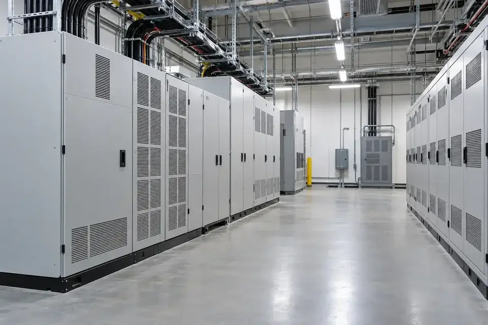
Closed backup-power cabinets along a clean industrial service aisle
Backup-power and UPS-room environment

UPS rooms can be exposed to water from cooling equipment, adjacent plant rooms or building services. A floor detection point can identify water entering an agreed external route near the room perimeter. Define this as building-water monitoring when specifying the project; battery electrolyte, battery condition and internal electrical protection require their own separately selected monitoring methods and equipment.
What to detect
Building-service water present at a selected UPS-room floor point.
Detection point
Cooling-service interfaces, room thresholds and approved floor low points outside UPS equipment.
Installation approach
Use locations approved by the facility and electrical teams. Preserve cabinet access and cable clearances, assess the installation environment and position the sensing assembly on the anticipated external water path.
Specify for your project
Share the UPS-room layout, nearby water services and the specific water-ingress concern.
Discuss this application

Motor-control and automation rooms

Water present at a selected automation-room boundary or floor route.
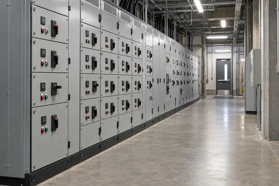
Closed motor-control centre panels along an industrial maintenance aisle
Motor-control room environment

Motor-control and automation rooms may sit beside wet production areas or receive services through shared walls and floor penetrations. Detection at an approved entrance or service-side low point can make unexpected water visible to the maintenance team through a named alert. Use the actual floor gradient and room boundary to select points, rather than placing sensors inside control cabinets by default.
What to detect
Water present at a selected automation-room boundary or floor route.
Detection point
Wet-area thresholds, service penetrations and accessible perimeter low points.
Installation approach
Agree the position with the control-room owner and electrical team. Protect the installation from carts and cleaning equipment, preserve access routes and confirm which normal cleaning events should produce a notification.
Specify for your project
Describe the adjacent process, floor slope, cleaning routine and preferred room or cabinet-row reference.
Discuss this application

Cable-trench water collection

Water reaching the selected trench low point or duct-entry collection area.
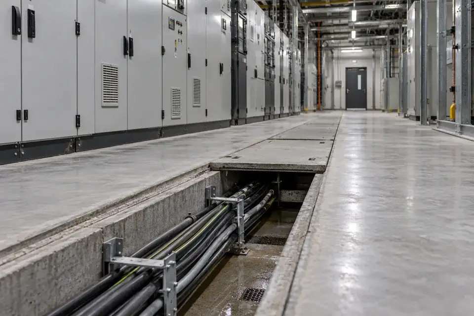
An open cable service trench beside closed industrial electrical cabinets
Cable service-trench environment

Cable trenches can collect water at low sections, duct entries or drainage interfaces that are hidden from everyday view. An approved detection point can report local water presence at a named trench section and guide an inspection. Check access, existing drainage and electrical working rules before choosing the installation; a reading describes the selected point rather than the condition of every cable route.
What to detect
Water reaching the selected trench low point or duct-entry collection area.
Detection point
Accessible trench sumps, drainage interfaces and approved low sections near duct entries.
Installation approach
Follow the site's electrical access and permit procedures. Fix the approved sensing assembly clear of cable supports and drainage paths, and arrange a maintainable route for inspection without disturbing installed circuits.
Specify for your project
Send the trench section, access method, drainage layout and electrical installation restrictions.
Discuss this application

Power-conversion plant rooms

Local water presence at a selected plant-room floor or entry interface.
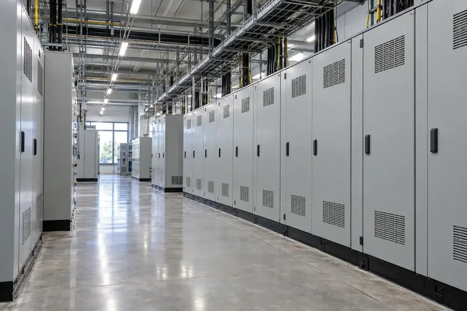
Closed electrical power cabinets in a bright industrial plant room
Electrical power plant-room environment

Inverter and power-conversion rooms can share a building envelope with water services, cooling circuits and outdoor cable entries. Local water detection at an approved floor or penetration interface helps identify which part of the room needs inspection. Separate equipment cooling-water concerns from rain ingress when mapping the points, and assign each alert to the facility team responsible for that route.
What to detect
Local water presence at a selected plant-room floor or entry interface.
Detection point
Approved cooling-service boundaries, external cable entry interfaces and room perimeter low points.
Installation approach
Select positions with the equipment owner and electrical team. Keep the sensing assembly outside energised equipment, preserve ventilation and service access, and confirm the environmental conditions of the approved detection location.
Specify for your project
Tell us the room type, equipment cooling arrangement and whether the concern is pipe water or weather ingress.
Discuss this application
04Data centres and telecom facilities5 monitoring tasks
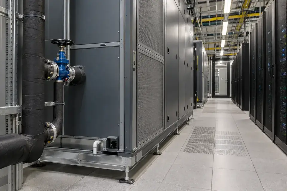
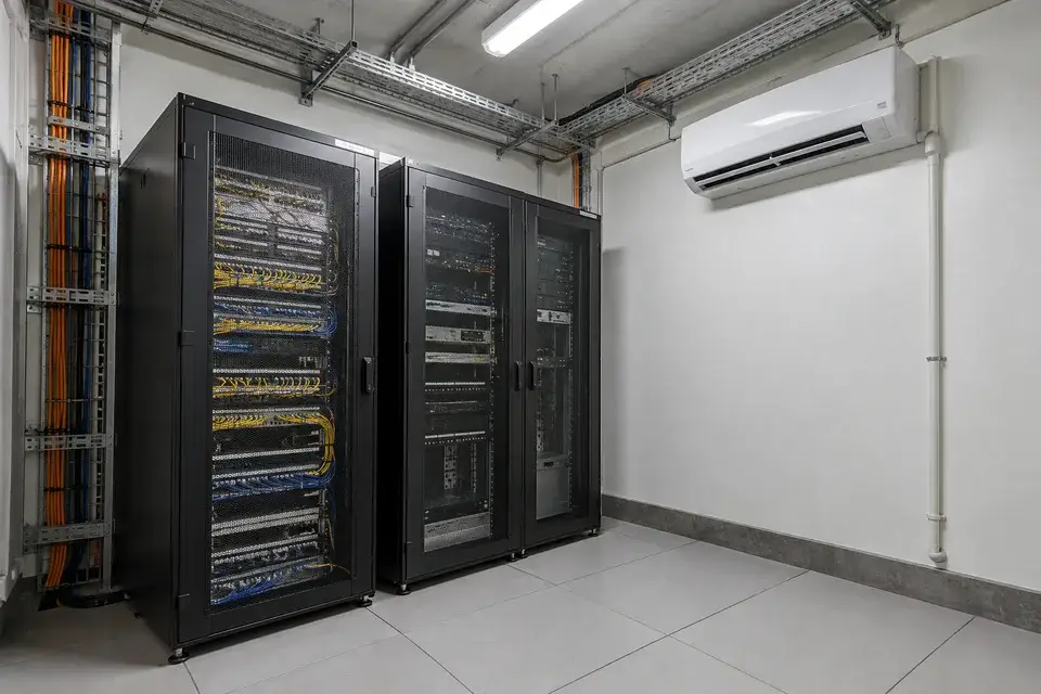
Data-centre cooling unit with accessible chilled-water connections beside server racks
Data-centre CRAH service environment

Give each cooling or water-routing area its own detection reference. Identify the CRAH unit, CDU connection, underfloor route or equipment room in the alert so the right team can investigate.

CRAH cooling-unit service areas

Water present at a selected CRAH connection or external collection point.
Data-centre cooling unit with accessible chilled-water connections beside server racks
Data-centre CRAH service environment

Chilled-water CRAH units combine water connections and condensate handling close to critical IT spaces. Place detection at selected valve-service or external collection positions to identify water outside the intended cooling and drainage routes. Name each point by the cooling unit and service side, so facilities staff can inspect the relevant connection or drain without treating every alert as a general room event.
What to detect
Water present at a selected CRAH connection or external collection point.
Detection point
CRAH water-valve service areas, external drain interfaces and approved collection trays.
Installation approach
Coordinate the position with the cooling-unit owner. Preserve filter, valve and drain access, avoid airflow obstruction and verify that normal condensate follows its intended route without continually wetting the selected detection point.
Specify for your project
Provide the CRAH layout, condensate route and required point naming by unit or service zone.
Discuss this application

CDU external water connections

Water or confirmed compatible cooling fluid reaching an external CDU collection point.
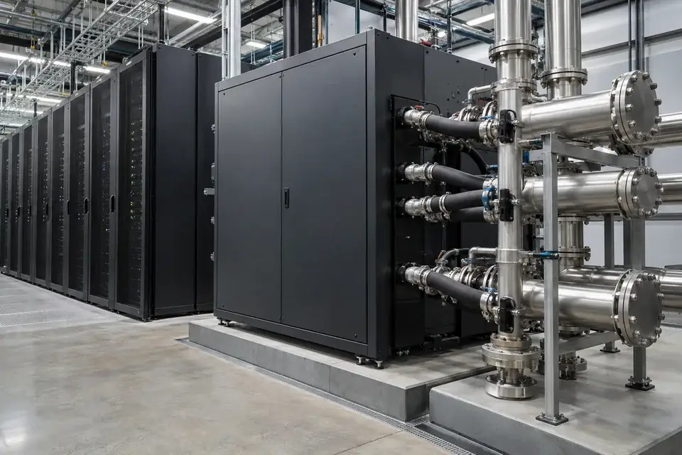
Data-centre cooling distribution cabinets with external stainless water connections
Data-centre CDU service environment

Liquid-cooled data centres may have coolant distribution units with external facility-water and technology-cooling connections. Select detection positions around the relevant connection bay or collection tray, then associate each point with the CDU and loop concerned. Specify the actual fluid formulation before selection, and keep leak detection distinct from coolant quality, flow, temperature and the equipment's internal protective functions.
What to detect
Water or confirmed compatible cooling fluid reaching an external CDU collection point.
Detection point
External CDU connection bays, service trays and selected facility-water interfaces.
Installation approach
Agree installation with the CDU supplier or facility owner. Keep hoses, quick connections and service doors accessible, confirm fluid compatibility and validate the selected collection point under the approved maintenance procedure.
Specify for your project
Share the CDU model, monitored loop, coolant composition and available external collection arrangement.
Discuss this application

Raised-floor service routes

Water present at a defined underfloor low point or service crossing.
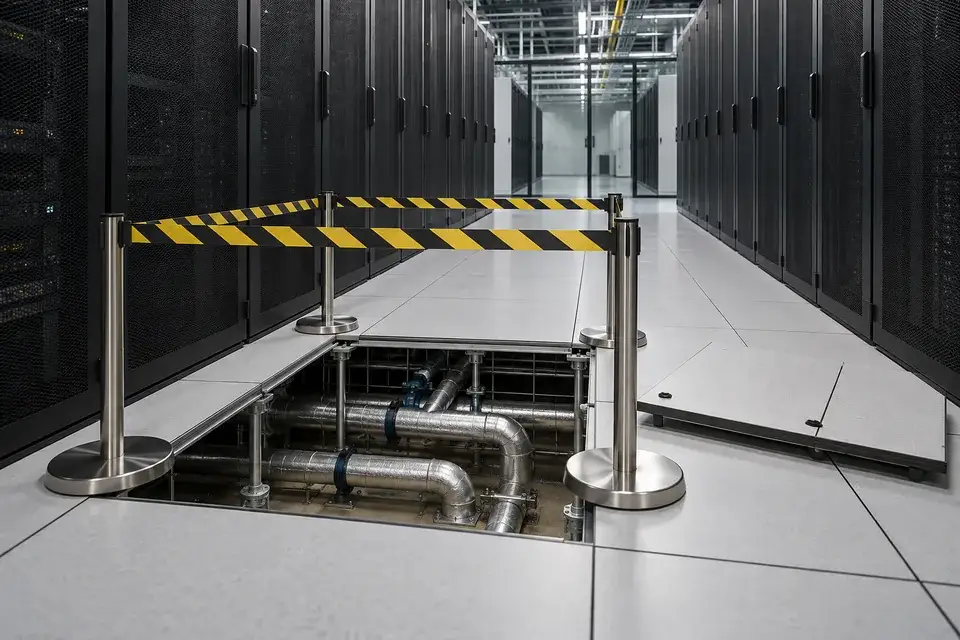
A guarded raised-floor opening exposing water-service pipes between server racks
Raised-floor service environment

Water entering a raised-floor space can travel along slab gradients and service routes before reaching a visible aisle. Detection at selected low points or pipe crossings helps facilities staff identify the area requiring inspection. Use a site survey to map water paths, floor access and equipment references; the sensing arrangement should be chosen for that layout rather than assuming a particular coverage distance.
What to detect
Water present at a defined underfloor low point or service crossing.
Detection point
Approved slab low points, water-pipe crossings and accessible underfloor collection routes.
Installation approach
Coordinate floor-panel access and work procedures with data centre operations. Keep the approved sensing assembly clear of airflow and cable supports, and label its position so staff can find it during inspection.
Specify for your project
Send the floor layout, relevant water routes and the access restrictions for the underfloor space.
Discuss this application

Telecom-room cooling drainage

Water reaching the selected cooling-drain or room perimeter point.
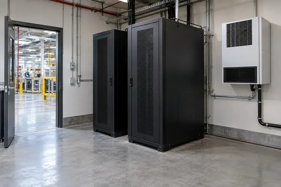
Telecom equipment racks beside a wall-mounted cooling unit and condensate drain route
Telecom-room cooling-service environment

Telecom equipment rooms may rely on local air-conditioning units whose condensate pipework crosses a restricted service area. A selected floor detection point can identify water escaping from a drain connection or reaching the room from adjacent services. Map the alert to the site and cooling zone, helping a remote maintenance team plan the appropriate inspection when the building is not routinely staffed.
What to detect
Water reaching the selected cooling-drain or room perimeter point.
Detection point
Air-conditioning drain interfaces, approved floor low points and room service-entry areas.
Installation approach
Use an accessible service-side position that preserves cooling airflow and rack access. Confirm the site's power and radio arrangement, protect exposed routing and test the intended notification path before the site is handed over.
Specify for your project
Specify the telecom site, cooling-drain layout, available radio coverage and maintenance contact route.
Discuss this application

Edge-computing service areas

Water present at a selected external rack-service or room-entry point.
Full-height industrial edge-computing cabinets beside a cooling unit and accessible floor in a factory service room
Industrial edge-computing service room

Edge-computing equipment can operate inside factories, transport buildings or other spaces where nearby water services remain outside the IT team's direct control. Detection at an agreed external rack-service or room-entry point can identify water arriving on that route. Establish who receives the alert, how the site is identified and which local team can inspect the installation when remote staff are responsible.

What to detect
Water present at a selected external rack-service or room-entry point.
Detection point
Approved rack perimeter collection areas, room thresholds and adjacent water-service boundaries.
Installation approach
Agree detection locations with both the IT operator and building owner. Preserve rack clearances and service access, assess the local environment and validate the full notification route using the ordered configuration.
Specify for your project
Tell us the edge-site type, nearby water sources and the local and remote teams involved.
Discuss this application
05Warehouses and critical storage5 monitoring tasks
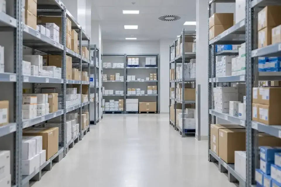
Automated high-bay warehouse aisle with stacked pallets and a stacker-crane rail route
Automated warehouse service environment

Choose detection positions around water-sensitive stock, packaging and collection storage. Floor gradients, rack bases, drainage and the route water could take matter more than an even spacing between sensors.

Automated warehouse floor routes

Water reaching a selected rack-base or warehouse floor collection point.
Automated high-bay warehouse aisle with stacked pallets and a stacker-crane rail route
Automated warehouse service environment

In automated warehouses, water can collect near rack bases, conveyor transfer points or low sections of an aisle while routine access is restricted. Select detection positions using the actual drainage route and equipment clearance plan. A clearly named local alert can help the warehouse and maintenance teams coordinate an inspection without requiring the sensing assembly to occupy a robot or shuttle travel path.
What to detect
Water reaching a selected rack-base or warehouse floor collection point.
Detection point
Approved rack-base low points, service-side transfer areas and accessible drainage interfaces.
Installation approach
Agree the location with the warehouse automation operator. Keep sensing components and routing outside moving-equipment envelopes, protect them from pallet impacts and provide an approved access route for testing and maintenance.
Specify for your project
Provide the automation layout, restricted travel zones and the floor-water routes of concern.
Discuss this application

Pharmaceutical warehouse water routes

Water present at a selected pharmaceutical storage-area floor point.
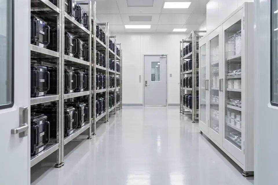
Organised boxed stock on shelving inside a clean pharmaceutical store
Pharmaceutical storage environment

Pharmaceutical stores may contain water-sensitive cartons, labels and packaged stock near cooling services, external walls or receiving areas. Detection at selected floor points can identify unexpected water entering a named storage zone. Build the response into the site's handling and quality procedures so staff can inspect the relevant storage zone and assess any affected stock.
What to detect
Water present at a selected pharmaceutical storage-area floor point.
Detection point
Approved storage-zone perimeters, cooling-service interfaces and receiving-area low points.
Installation approach
Agree positions with warehouse and quality personnel. Keep the assembly clear of stock handling and cleaning routes, use approved fixing methods and document the point location within the site's inspection procedure.
Specify for your project
Share the storage layout, packaging sensitivity, nearby water services and the required inspection records.
Discuss this application

Wafer and electronics material stores

Water reaching an approved external storage-room or rack perimeter point.
Semiconductor material storage room with sealed wafer transport carriers, enclosed storage and a clear floor aisle
Wafer-carrier and electronics storage environment

Semiconductor materials and electronic assemblies may be stored near facility-water routes even when their own packaging is sealed. Water detection at an approved external room or rack perimeter can identify an event that calls for facilities inspection and stock assessment. Coordinate the selected position with contamination-control and handling requirements, while leaving package integrity, humidity control and material acceptance to their dedicated procedures.
What to detect
Water reaching an approved external storage-room or rack perimeter point.
Detection point
Storage-room thresholds, external water-service interfaces and approved perimeter low points.
Installation approach
Use positions and fixing methods approved by facilities and contamination-control personnel. Keep the assembly outside sealed carriers and sensitive storage enclosures, and preserve handling clearances and the area's cleaning access.
Specify for your project
Describe the stored materials, room classification, packaging arrangement and permitted external installation positions.
Discuss this application

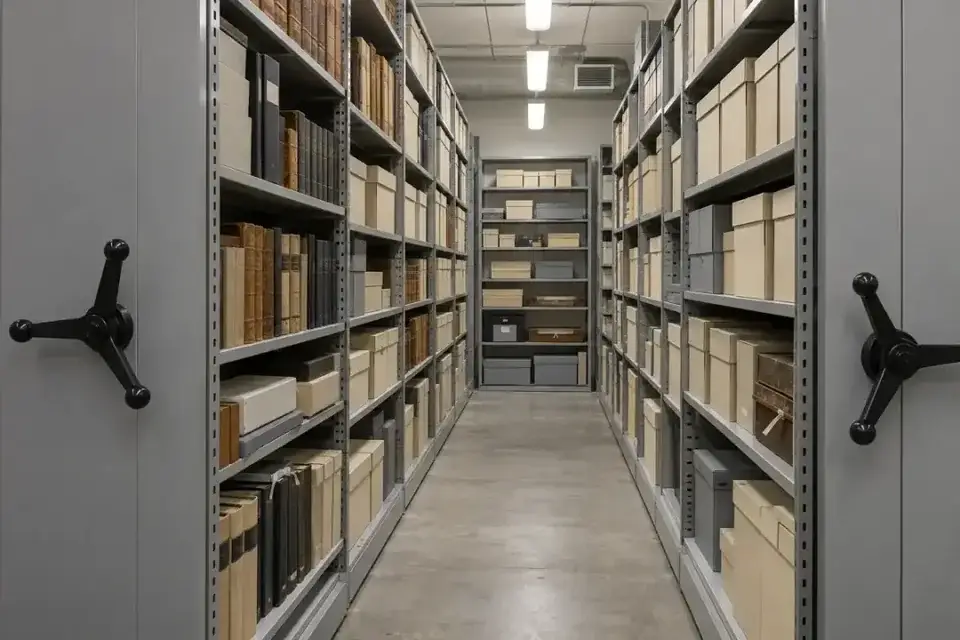
Museum and archive storage rooms

Water present at a selected collection-store floor or perimeter point.
Archival boxes on compact museum or archive shelving with a clear floor aisle
Archive storage environment

Collection stores can be affected by water from building services, roof drainage or adjacent rooms. Detection at a chosen perimeter or low point can identify water entering an area holding boxed objects, documents or conservation materials. Select positions with the collection-care team so installation, inspection and response fit the room's storage layout, handling practices and approved methods for working near collections.

What to detect
Water present at a selected collection-store floor or perimeter point.
Detection point
Approved shelving perimeters, service-entry low points and storage-room thresholds.
Installation approach
Agree reversible or otherwise approved fixing methods with the collection-care team. Keep the sensing assembly clear of objects and shelving movement, and document an accessible inspection route that respects collection handling procedures.
Specify for your project
Tell us the collection type, storage layout, potential water sources and approved installation methods.
Discuss this application

Paper and packaging-material stores

Water reaching a selected paper or packaging storage-area collection point.
Paper rolls and stacked packaging stock beside an accessible warehouse service aisle
Paper and packaging-material storage environment

Paper rolls, corrugated cartons and packaging materials can be stored close to receiving doors, external walls or utility routes. Local detection at selected floor collection points gives the maintenance team a reference when water reaches an unintended storage area. Use the actual pallet arrangement and floor gradient to choose positions, keeping the sensing assembly accessible as stock locations change during normal warehouse operations.
What to detect
Water reaching a selected paper or packaging storage-area collection point.
Detection point
External-wall low points, receiving thresholds and approved service-side pallet perimeters.
Installation approach
Position the approved assembly outside forklift and pallet handling paths. Protect it from stock impacts, keep cleaning access available and review point locations when storage layouts or receiving procedures change.
Specify for your project
Share the material type, stock layout, vehicle routes and likely floor-water entry points.
Discuss this application
06Process and laboratory support5 monitoring tasks
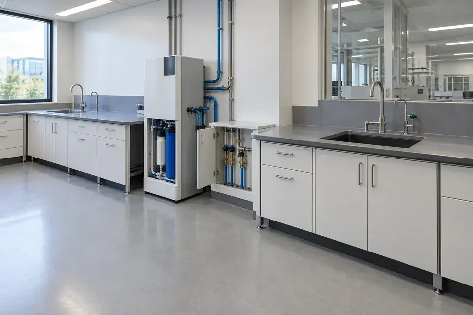
Laboratory water-service workspace with complete benches, sinks, a purification unit, service connections and accessible floor
Laboratory bench and water-service environment

Watch the external water-service areas that support controlled processes. Specify fluid compatibility, cleaning conditions and access requirements for laboratories, cleanroom utilities, pharmaceutical production and industrial washing.

Laboratory water-service areas

Water present at a selected laboratory water-service collection point.
Laboratory water-service workspace with complete benches, sinks, a purification unit, service connections and accessible floor
Laboratory bench and water-service environment

Laboratories may have purification units, sinks, wash stations and water-cooled equipment connected through benches or service cupboards. Detection at an approved external collection point can identify water escaping from these services. Confirm the actual water quality and any expected cleaning or process residues before selection, and associate the alert with the bench, equipment area or utility cupboard that staff should inspect.
What to detect
Water present at a selected laboratory water-service collection point.
Detection point
Water-purifier bases, approved sink-service areas and external water-cooled equipment trays.
Installation approach
Agree positions with the laboratory manager and facilities team. Keep the assembly outside chemical-handling zones unless specifically assessed, preserve bench access and validate the chosen sensing method with the actual water stream.
Specify for your project
Provide the water-service layout, water quality, expected residues and permitted installation areas.
Discuss this application

Cleanroom utility perimeters

Water present at a selected external cleanroom utility-service point.
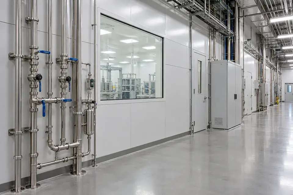
External cleanroom utility corridor with water-service pipes, closed utility cabinets, a viewing window and a clear floor perimeter
Cleanroom perimeter utility-service corridor

Semiconductor and precision-manufacturing facilities route cooling and process-support water through service corridors and utility chases outside the controlled production area. A selected water-detection point can identify wetness in one of these accessible support zones. Define the monitored water stream, installation boundary and contamination-control requirements with facilities staff, so an alert names the relevant utility section without implying coverage of process-chemical distribution.
What to detect
Water present at a selected external cleanroom utility-service point.
Detection point
Approved cooling-water service corridors, utility-chase low points and external collection trays.
Installation approach
Install only within the approved utility boundary and follow the site's access and cleanliness procedures. Confirm water compatibility, keep service clearances available and label the point with the correct utility-loop reference.
Specify for your project
Specify the utility water stream, controlled-area boundary, access rules and naming convention.
Discuss this application

Pharmaceutical water-utility support

Compatible water reaching a selected external utility-support collection point.
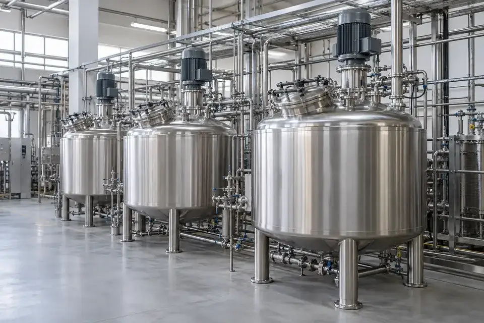
Stainless process vessels with external water and service pipework
Stainless utility-vessel environment

Pharmaceutical facilities may need local water detection around external treatment skids, valve stations and support-room collection points. Specify the monitored water stream and expected temperature, particularly where low-conductivity water or hot services are involved. Label the point by utility loop and support room so the facilities team can inspect the relevant skid, valve station or collection area and document its response.
What to detect
Compatible water reaching a selected external utility-support collection point.
Detection point
Approved treatment-skid bases, external valve-service bays and suitably tempered collection areas.
Installation approach
Agree the position and fixing method with engineering and quality personnel. Keep the assembly outside the hygienic water circuit, verify fluid temperature and conductivity, and use the site's approved cleaning and access procedures.
Specify for your project
Share the water grade, potential release temperature, cleaning regime and facilities documentation requirements.
Discuss this application

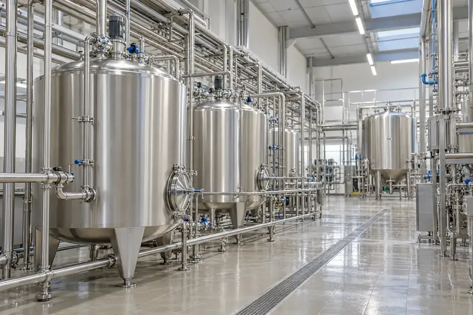
Food-production water utility rooms

Water present at an agreed utility point expected to remain dry in normal operation.
Stainless tanks and service pipework in a clean food or beverage plant
Food-production utility environment

Food and beverage plants use treated water, rinsing services and cooling circuits in utility areas that may also experience regular washdown. Detection is most useful where the selected point has a clearly defined normal condition. Agree whether the project concerns unexpected standing water, a particular service connection or a dry boundary beside production, and include cleaning chemicals and hygiene requirements in selection.
What to detect
Water present at an agreed utility point expected to remain dry in normal operation.
Detection point
Approved water-treatment skid perimeters, dry service boundaries and connection-area collection trays.
Installation approach
Choose locations with production and hygiene personnel. Keep components clear of food-contact surfaces and cleaning traffic, confirm chemical and environmental compatibility, and agree how scheduled washdown is handled in the notification workflow.
Specify for your project
Tell us the water service, normal wet or dry state, washdown process and required hygiene restrictions.
Discuss this application

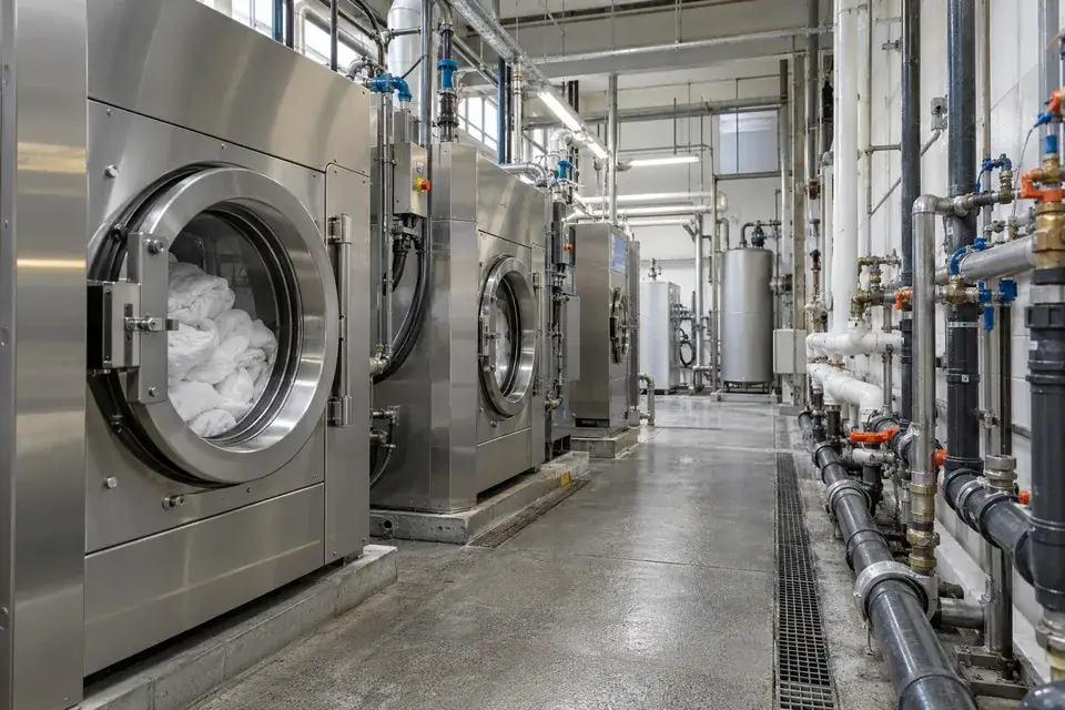
Industrial laundry water-service zones

Compatible water reaching an agreed dry service-zone detection point.
Commercial laundry machines beside external water pipes in an industrial service aisle
Industrial laundry water-service environment

Industrial laundries combine washer connections, water supply manifolds and drain routes with frequent cleaning and material movement. A selected detection position can identify water entering a service area that should remain dry during normal operation. Check the expected water temperature and detergent residues before configuration, then define how staff distinguish an equipment-service event from planned washdown or an intentionally wet drainage area.
What to detect
Compatible water reaching an agreed dry service-zone detection point.
Detection point
External washer-service connections, water-manifold bases and approved dry-zone collection points.
Installation approach
Place the approved assembly outside hot discharge paths, laundry carts and moving machinery. Confirm fluid and cleaning compatibility, keep drain access unobstructed and test the selected point against normal operating and washdown conditions.
Specify for your project
Provide the washer layout, water temperature, detergent exposure and the dry service zones to monitor.
Discuss this application
07Below-grade and building services5 monitoring tasks
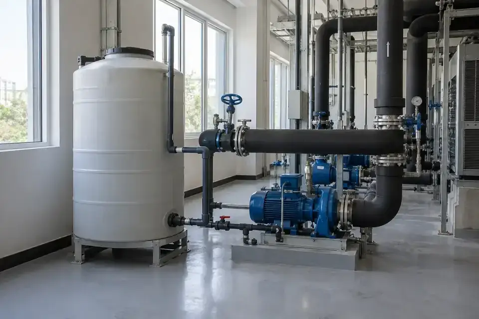
Water makeup tanks, booster pumps and exposed service pipes in a plant room
Plant-room water-service environment

Low points, service penetrations and concealed pipe routes can carry water away from its source. Select accessible detection positions and name the area clearly in the inspection and response plan.

Basement plant and pump rooms

Water present at a selected basement plant-room floor point.
Water makeup tanks, booster pumps and exposed service pipes in a plant room
Plant-room water-service environment

Basement plant rooms can receive water from equipment connections, building penetrations or adjacent low-level spaces. Detection at a selected floor low point can identify local accumulation and direct an inspection to the relevant room. Review normal drainage and sump operation when mapping the points, and keep water-presence notification separate from pump control or continuous measurement of the sump's liquid level.
What to detect
Water present at a selected basement plant-room floor point.
Detection point
Approved floor low points, plant-room thresholds and external equipment collection areas.
Installation approach
Select a maintainable point using the room's floor gradient and normal drainage pattern. Keep the assembly clear of sump mechanisms and access routes, and confirm environmental conditions at the chosen detection position.
Specify for your project
Share the basement layout, normal drainage arrangement, sump equipment and water-entry routes of concern.
Discuss this application

Utility galleries and service corridors

Water reaching a selected gallery low point or service-route collection area.
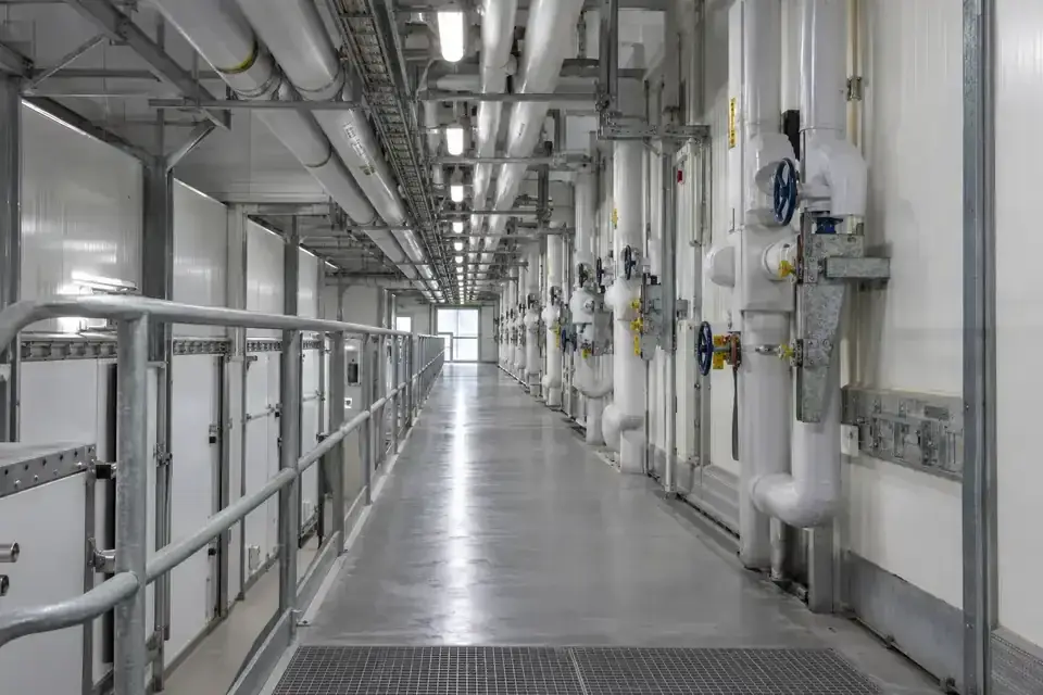
Industrial utility corridor with insulated pipework and accessible valve stations
Utility service-corridor environment

Service galleries can carry water away from a pipe joint through shared channels and floor gradients. A named detection point at an accessible low section can help maintenance staff identify where water has collected and plan their inspection. Divide long routes according to actual drainage boundaries and access points, with the sensing arrangement selected for each section rather than an assumed universal monitoring length.
What to detect
Water reaching a selected gallery low point or service-route collection area.
Detection point
Accessible channel low points, pipe-service collection areas and gallery drainage interfaces.
Installation approach
Use approved gallery access and working procedures. Keep sensing components clear of pipe supports, walking routes and drainage, and label the location so inspection teams can identify the correct section promptly.
Specify for your project
Provide the gallery plan, drainage boundaries, access restrictions and desired section references.
Discuss this application

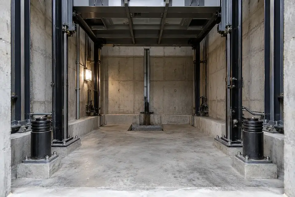
Approved lift and freight-lift pits

Water reaching an approved collection point within the lift-pit installation area.
The lower pit and buffer structures of a freight lift viewed from a maintenance access point
Freight-lift maintenance environment

Water may collect in a lift pit through building ingress, nearby services or drainage problems. A local detection position can be considered as part of an installation approved by the lift owner and maintenance provider. Define the pit access method, equipment clearances and response procedure before selection, with the lift's own controls and protective functions remaining under the responsible specialist's authority.
What to detect
Water reaching an approved collection point within the lift-pit installation area.
Detection point
Lift-maintainer-approved pit low points or external collection positions identified in the site assessment.
Installation approach
Proceed only with the lift owner and maintenance provider's approval and access arrangements. Keep the assembly outside moving equipment and required clearances, using approved fixings and an agreed inspection and testing procedure.
Specify for your project
Share the lift type, approved pit access arrangements and the maintenance provider's installation requirements.
Discuss this application

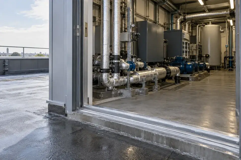
Rooftop plant-room ingress

Water present at a selected internal plant-room collection or entry point.
Rooftop plant-room doorway opening onto pumps and insulated building services
Rooftop plant-room environment

Rooftop plant rooms combine equipment water services with doors, roof penetrations and drainage interfaces exposed to weather. Select detection positions according to the water route of concern: pipe leakage, condensate escaping its drain or rain entering the room. Clear point naming helps the facility team inspect the relevant interface and distinguish a building-envelope issue from an equipment-water service event.
What to detect
Water present at a selected internal plant-room collection or entry point.
Detection point
Approved internal doorway low points, roof-service penetrations and equipment-service collection areas.
Installation approach
Confirm the actual exposure at the chosen point and select the enclosure and sensing configuration accordingly. Preserve drainage and roof access, and keep the assembly clear of hot equipment and service routes.
Specify for your project
Tell us whether the concern is weather ingress, cooling water or condensate, and provide the room layout.
Discuss this application

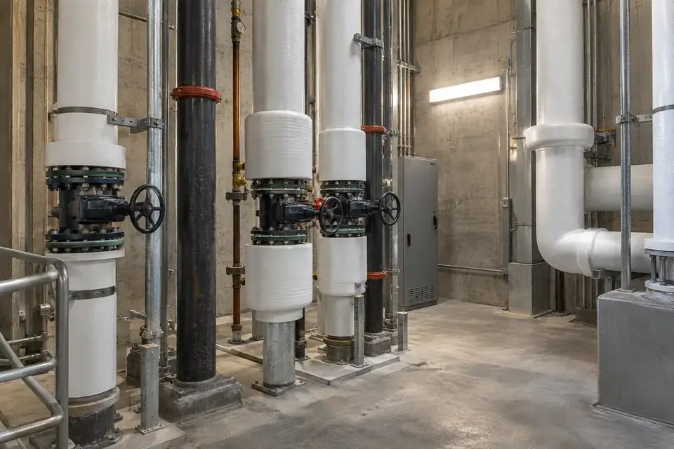
Mechanical risers and service shafts

Water present at a selected accessible riser or shaft collection point.
Insulated vertical water-service pipes and valves inside an accessible mechanical riser
Mechanical water-service riser environment

Water escaping inside a mechanical riser can travel between floors along pipework, penetrations and service ledges. Detection at an approved accessible collection position can identify water reaching a named riser section. Select points from the building layout and expected water path, while preserving fire-stopping, service access and the inspection procedure for shafts that are not routinely open to facility staff.
What to detect
Water present at a selected accessible riser or shaft collection point.
Detection point
Approved service ledges, riser-base collection areas and accessible pipe-entry low points.
Installation approach
Agree mounting and access with the building-services team. Preserve fire-stopping and pipe clearances, avoid obstructing maintenance doors and use approved routing and fixings suitable for the selected service-shaft location.
Specify for your project
Provide the riser arrangement, water-service routes, approved access locations and fire-stopping restrictions.
Discuss this application
08Outdoor industrial infrastructure5 monitoring tasks
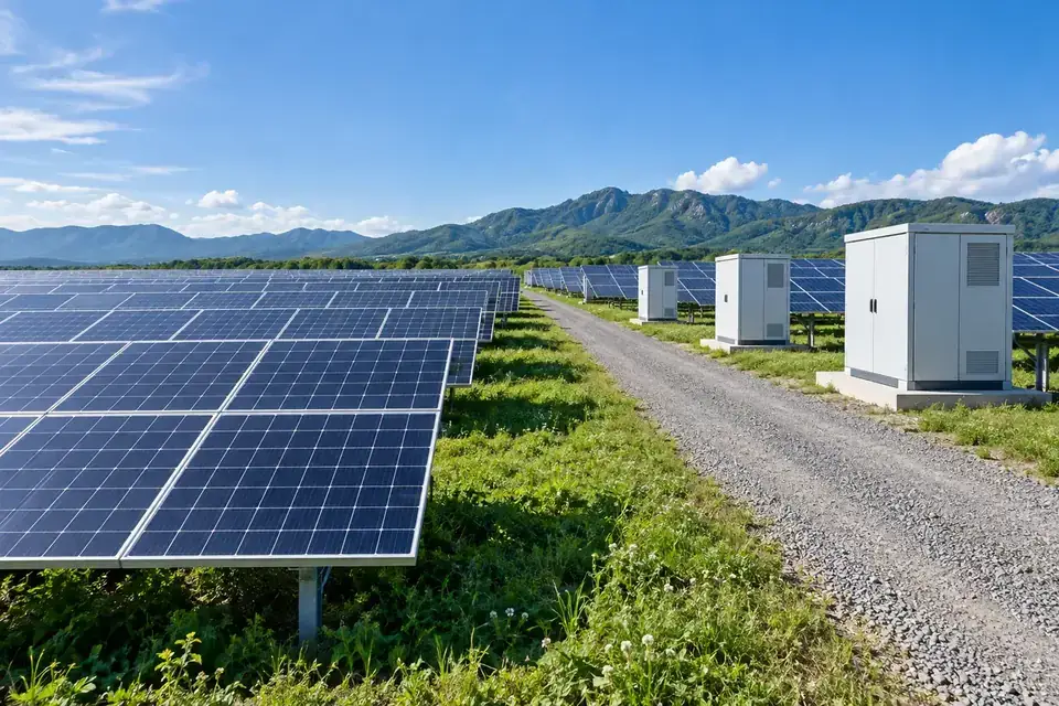
Photovoltaic arrays and a closed outdoor electrical support cabinet on a service base
Outdoor energy-site cabinet environment

For outdoor projects, define whether the task is ingress detection, unexpected local water or drainage inspection. Rainfall, washdown and normal runoff belong in the site specification and alarm logic.

Outdoor cabinet plinths and bases

Water reaching an approved cabinet-base or plinth detection point.
Photovoltaic arrays and a closed outdoor electrical support cabinet on a service base
Outdoor energy-site cabinet environment

Outdoor control and communications cabinets may be exposed to water entering through their base, cable ducts or a damaged building interface. A selected detection point inside an approved lower service zone can identify local ingress. Confirm the cabinet environment, drainage arrangement and expected wet conditions before configuration, giving the alert a cabinet reference that a field technician can use during inspection.
What to detect
Water reaching an approved cabinet-base or plinth detection point.
Detection point
Approved lower cabinet service areas, cable-entry collection points and sheltered plinth interfaces.
Installation approach
Agree the position with the cabinet owner and electrical team. Select protection for the actual exposure, preserve seals and ventilation, and keep sensing components clear of live equipment, drainage openings and service access.
Specify for your project
Send the cabinet and plinth layout, weather exposure, duct-entry arrangement and approved installation zone.
Discuss this application

Substation drainage interfaces

Water present at a selected, approved substation drainage or entry point.
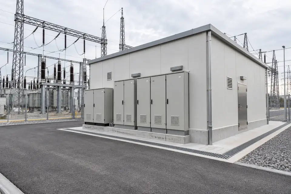
Substation auxiliary building with closed control cabinets and an external drainage channel
Substation auxiliary-building environment

Substation buildings and cable-entry areas can have low points where water collects before it becomes visible from the access route. Detection at an approved drainage or perimeter interface can identify water at that specific location. Coordinate the point layout with the site's electrical and drainage teams, then link each alert to the approved collection point and inspection route.
What to detect
Water present at a selected, approved substation drainage or entry point.
Detection point
Approved building-entry low points, sheltered cable-duct interfaces and accessible drainage collection positions.
Installation approach
Follow the substation owner's access, clearance and electrical work rules. Select the approved assembly for the actual exposure, maintain drainage and test the point under the site's agreed commissioning procedure.
Specify for your project
Provide the approved installation area, drainage plan, weather exposure and electrical working restrictions.
Discuss this application

Tunnel maintenance and service areas

Water present at a selected tunnel service-area collection point.
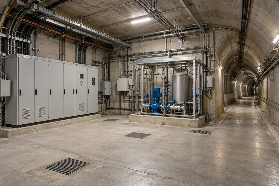
Tunnel maintenance alcove with complete control cabinets, pumping equipment, covered drains and an accessible dry service passage
Tunnel maintenance and water-service alcove

Tunnel maintenance areas may contain drainage services, water supply connections or equipment rooms reached through restricted access routes. Local detection at an approved collection position can identify water reaching a named service zone. Establish normal seepage and cleaning conditions before specifying alerts, and check the available communications path so the notification arrangement reflects the actual underground installation and maintenance workflow.
What to detect
Water present at a selected tunnel service-area collection point.
Detection point
Approved maintenance-room low points, service connection trays and accessible drainage interfaces.
Installation approach
Use the tunnel operator's approved access and fixing procedures. Keep the assembly clear of traffic and maintenance equipment, confirm environmental suitability and verify communications and notification delivery at the actual underground position.
Specify for your project
Share the service-area layout, normal seepage, access rules and available radio or gateway arrangement.
Discuss this application

Outdoor water-pipeline valve areas

Water reaching a selected water-pipeline valve-area collection point.
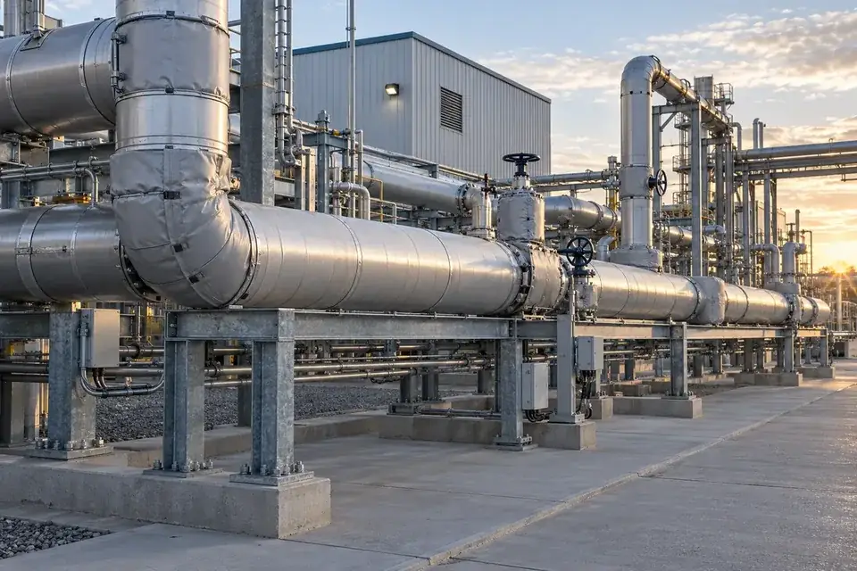
Outdoor industrial service pipework with accessible valves and a paved service base
Outdoor pipeline and valve-service environment

Outdoor industrial water networks contain valve stations, flange joints and service chambers where local water can accumulate. Choose a detection point with a defined expected state, accounting for rainfall, irrigation and normal drainage. A water-presence alert can guide inspection of the named area; identifying the release source still depends on the site's pipe layout, operating conditions and maintenance checks.

What to detect
Water reaching a selected water-pipeline valve-area collection point.
Detection point
Approved sheltered valve-station trays, accessible service-chamber low points and defined dry collection areas.
Installation approach
Select the assembly for the site's exposure and approved access conditions. Keep valves and drainage accessible, protect against vehicle or maintenance impacts and agree how normal rain or washdown affects notification handling.
Specify for your project
Tell us the water service, expected wet conditions, chamber access rules and intended inspection area.
Discuss this application

Loading-bay and dock water routes

Water reaching an agreed dry boundary or loading-bay collection point.
Truck positioned at a sheltered warehouse loading dock beside a clear paved apron
Warehouse loading-dock environment

Loading bays can receive rainwater, washdown and water from adjacent industrial services, with floor gradients directing it toward doors or equipment recesses. Select detection points at agreed dry boundaries or collection positions that matter to operations. Define which conditions require inspection so staff can distinguish normal outdoor wetness from water reaching a protected service area, dock recess or storage entrance.

What to detect
Water reaching an agreed dry boundary or loading-bay collection point.
Detection point
Approved dock-service recesses, sheltered doorway low points and protected storage-entry boundaries.
Installation approach
Keep the assembly outside truck, forklift and dock-leveller movement zones. Select protection for actual weather and washdown exposure, preserve drains and agree the normal wet-state behaviour before validating the notification workflow.
Specify for your project
Provide the dock layout, vehicle movement zones, drainage route and the boundary that should remain dry.
Discuss this application

SERIES & CONFIGURATION

Choose the connection.
Configure the sensing point.

The H Series water-leak family separates the wireless connection from the sensing and installation requirements. H200 is LoRa, H300 is 4G and H500 is NB-IoT. H300-WL002A is the specified H300 model; define the liquid, monitored position, supplied sensing assembly and response workflow with the selected terminal.

NB-IoT

H500

For supported NB-IoT networks. Confirm operator availability, coverage and the required event-delivery behaviour.

Discuss this configuration ↗
H Series wireless water leak sensors — model and configuration reference
Specified 4G modelH300-WL002A
Wireless family mappingH200 — LoRa / H300 — 4G / H500 — NB-IoT
Monitoring taskPresence of water at the selected sensing location; event state and recovery behaviour confirmed for the supplied configuration
Sampling intervalSet according to customer requirements.
Sensing arrangement & coveragePoint detection at the installed probe location. Confirm the number and arrangement of sensing points for the site.
Liquid suitabilityActual water or condensate, additives, conductivity, contamination and contact-material compatibility reviewed for the application
Power arrangementConfirmed for the ordered terminal, sensing assembly and installation
Detection, reporting & responseRequired behaviour and end-to-end timing agreed and verified at commissioning
Operating environment & protectionTemperature, humidity, wet exposure, enclosure protection and mounting confirmed for the final configuration
Receiving platformHitelecom Cloud or an agreed compatible customer system; connection and event format confirmed
Local interfaces & actionsAny required local alarm, valve or equipment interface assessed separately as part of the site control design
Inspection & commissioningControlled detection test, received notification, recovery check and environment-specific maintenance plan

Specify the detection point and the response.

01

Define the water event

Liquid type · Possible sources · Detection points · Required coverage

02

Define the installation

Sensing construction · Mounting · Floor and drainage layout · Power arrangement · Access

03

Define the response

H200 / H300 / H500 · Receiving system · Notification timing · Recipients · Recovery

CONNECTIVITY & INTEGRATION

Hitelecom platform.
Connect the event to your workflow.

Define whether the receiving destination is Hitelecom Cloud or a compatible customer system, then confirm the message format, supported connection and event rules for the supplied configuration. Agree device and sensing-point identifiers and notification recipients; confirm the supported event, status and reporting behavior from the supplied documentation. Local warning, valve or machine actions need their own interface and control design.

H300 · 4G / H500 · NB-IoT

Connect distributed sites.

Detection pointMobile networkPlatform

Match the regional bands and operator coverage to the installation country. Check the signal where the transmitter will be installed, including plant rooms and below-ground locations.

  • Country, operator and network availability
  • Device power and reporting requirements
  • Alert delivery and responsible recipients
H200 · LoRa

Connect points across one site.

Detection pointsReceiver / gatewayPlatform

Match the supplied LoRa protocol and regional settings to the receiver or gateway. Confirm LoRaWAN compatibility explicitly when the project requires it.

  • Device protocol and receiver compatibility
  • Coverage through walls, floors and equipment
  • Gateway power and onward connection

Test the complete alert path.

Identify each detection point in a sample message. Confirm the supported payload fields, alarm states, reporting schedule and recovery behavior with the sample message from the ordered configuration. Test alert receipt and the site response before handover.

Discuss platform integration ↗

ANSWERS FOR YOUR PROJECT

Frequently asked questions.

Practical answers for selecting water-detection points, choosing the connection and preparing a useful commissioning and response plan.

Ask about your project ↗
What does a wireless water leak sensor detect?

It monitors for water reaching the installed sensing location and makes the detected condition available to a remote monitoring system through the selected wireless connection. Position the sensing element where leaked water is expected to reach it. The sensing construction and reported states are agreed for the supplied configuration.

How is water leak detection different from liquid-level measurement?

Leak detection answers whether water has reached a selected monitoring point or sensing path. Continuous liquid-level measurement measures the height or depth of liquid in a tank or vessel. Choose the product by the operational question: unwanted water at a location, or an actual level value.

Which connection should I choose: LoRa, 4G or NB-IoT?

Choose H200 for LoRa, H300 for 4G, or H500 for NB-IoT. Confirm radio coverage, the receiving infrastructure or network subscription, the destination platform and the required reporting behaviour at the planned installation. H300-WL002A is the 4G model specified for this page.

Where should a water leak sensor be installed in a factory?

Start with likely leak sources, the route water will follow, and assets that need an early maintenance response. Typical positions include drip trays, pipe joints, pump bases, cooling skids and designated low points near equipment. Keep sensing surfaces accessible for inspection and apply the approved mounting and electrical-work rules.

Where does the two-pin point probe detect water?

It detects water reaching the installed probe location. For several collection points, plan the sensing positions around the likely water paths and confirm the required number and arrangement of point probes. Discuss route or perimeter coverage as a separate sensing design.

Can the sensor be used for condensate, deionized water or process liquids?

Select the sensing assembly for the actual liquid. Conductivity, contamination, temperature and contact materials can affect detection. For condensate, purified water, glycol mixtures or process liquids, confirm suitability with a representative liquid sample and the supplied configuration before rollout.

How should remote notifications be commissioned?

Test the water alarm, received notification and any supported recovery indication according to the supplied instructions. Record the end-to-end timing under the site's network conditions.

Can water leak monitoring trigger a shut-off valve or machine action?

If a shut-off or equipment response is needed, define it as part of the site control design. Confirm the required interface, power, control logic, fail-state behaviour and commissioning method. Agree this integration separately from the wireless monitoring function.

What should be checked during routine maintenance?

Inspect the sensing surface and expected water path for dirt, damage, moved equipment or cleaning residues. Follow the supplied cleaning instructions and repeat a controlled detection and recovery check at intervals chosen for the environment and maintenance plan.

What information helps you configure a water leak monitoring project?

Send the application, country, liquid type, likely leak points, coverage area, installation photos and quantity. Include the preferred H200 LoRa, H300 4G or H500 NB-IoT connection, platform destination, required notification path and any local control requirement. We can then review the sensing arrangement and project configuration.

LET’S TALK ABOUT YOUR PROJECT

Show us the water risk.
We’ll help define the sensing plan.

Tell us the application and where unwanted water could appear. Add a site photo or layout when you contact us; we can review the sensing arrangement, wireless choice and response requirements before preparing a configuration and quotation.

sales@hitelecom.cn ↗

A useful first conversation.

A short description is enough to start. Useful details include the water or condensate involved, likely leak sources, monitored area, installation country, quantity and receiving platform.

PROJECT ENQUIRY

Let’s find your configuration.

H Series wireless water leak monitoring

Detection and integration details Optional

Review and edit the brief, then copy it or open your email app to send. This page does not automatically send the enquiry.

You can also email your project details directly.