



Wireless liquid level sensors.
Know the level.
Plan the next action.
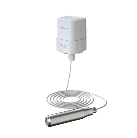
Hitelecom H Series submersible level sensors bring readings from tanks, sumps, wells and water sites into your monitoring platform. Configure the level range, probe cable and installation around the liquid, vessel and operating conditions, then select a 4G, NB-IoT or LoRa variant. From factory water reserves to effluent collection, a defined sensing point helps your team follow replenishment, drawdown and high or low level events between site visits.
KEY FEATURES
Track liquid levels.
Connect the next decision.
Bring the liquid, required span, installation conditions and data destination into one monitoring plan.
Liquid-level visibility
Follow storage, replenishment and collection trends at your selected tanks, sumps and wells.
±0.5% FS accuracy
Choose the full-scale span for your required level tolerance. Higher-precision configurations can be discussed.
Up to 200 m
Configure the published range around the liquid depth, reference point and monitoring task.
IP68 protection
Published IP68 protection, with component placement and immersion conditions defined for your configuration.
Wireless connectivity
Select 4G LTE, NB-IoT or LoRa around site coverage and the receiving platform.
NFC & remote OTA
Supported NFC activation and local setup, with remote firmware updates for the selected configuration.
Long-life monitoring
Published battery reference: more than 10 years at four-hour reporting, with runtime reviewed for your operating profile.
Project configuration
Match range, probe cable, mounting, reporting and high / low alerts to the installation.
DEFINE WHAT YOUR LEVEL PROJECT NEEDS
Choose the range.
Define the sensing point.
Useful level data starts with a clear reference position and a span matched to the task. Specify the liquid, maximum level and required tolerance, then match the probe, cable and installation to the tank, sump, well or water site.
Level range & accuracy
The published family covers 0–200 m with customization available. Choose the full scale for the actual task, and translate percentage-of-full-scale accuracy into the level tolerance your operation needs.
- Define your measurement
- Maximum level · Reference depth · Required tolerance · Alarm setpoints
Liquid & vessel conditions
Share the medium, temperature, solids and tank pressure so probe and cable suitability can be reviewed. For a pressure-based configuration, include liquid density and the pressure-reference arrangement in selection.
- Define your measurement
- Liquid composition · Density · Temperature · Open or pressurized vessel · Fouling
Installation & connectivity
Plan a stable probe position and an accessible wireless terminal. Agree cable routing, mounting, network coverage and the receiving platform as one deployment, with practical access for inspection.
- Define your measurement
- Probe position · Cable route · Terminal mounting · Coverage · Platform
Set a clear level reference.
Keep the installation practical.
Document the probe reference point, maximum immersion and the relationship between the reading and the site's level marks. Select a position away from strong inlet turbulence, with suitable support and access for inspection. Plan cable routing around abrasion, tension and service work. Mount the communication terminal for reliable reception and maintenance access. Confirm the supplied probe, cable, pressure reference and component limits before commissioning the complete data path.
FROM LEVEL READING TO SITE ACTION
See the level trend.
Give the team a useful next step.
Choose sampling and reporting around the rate of level change and the response your team needs. A storage tank replenished slowly may use a different profile from a small collection sump. Reporting settings and platform alarms should be commissioned together, including data timing and the assigned follow-up. For pump control, define the controller path and response requirements as part of the complete system.
Measure
The selected probe records level at a defined tank, sump or well point. Agree the reference, range, liquid conditions and sampling profile before deployment.
Transmit
Readings follow the selected wireless path. Verify coverage, reporting, message format and delivery to Hitelecom Cloud or the agreed receiving platform.
Review
Compare replenishment, drawdown and collection trends with site operations. Set thresholds and agree who reviews an alert or visits the monitoring point.
The published reference is more than 10 years of battery life at a four-hour reporting interval under specified test conditions. Review the estimate for the selected model and deployment. Sensing configuration, sampling demand, reporting frequency, network coverage, retransmissions and operating temperature affect runtime. Match the monitoring profile to the process and confirm the battery-life estimate with the ordered configuration.
APPLICATIONS
Liquid level monitoring applications.
40 defined monitoring contexts.
Explore eight application groups across factory water storage, cooling utilities, process water, effluent recovery, drainage, industry-specific water systems, dewatering and source water. Each context identifies the level trend, sensing point and project details that help select a useful configuration.
8 application categories 40 monitoring tasks
Illustrative application images. Configure each monitoring point for the actual liquid and installation.
01Factory water storage5 monitoring tasks +
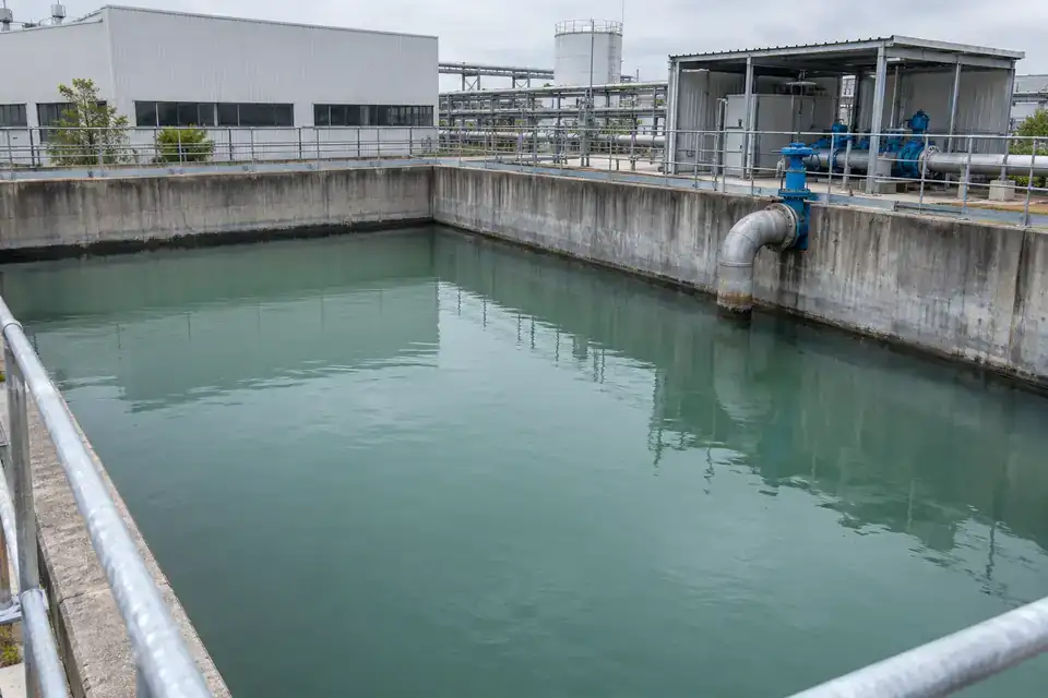
Follow the water stored between incoming supply and industrial demand. Select each monitoring point around usable depth, the refill arrangement and the team’s chosen reserve level.
Factory raw-water buffer tanks
Liquid height and replenishment / drawdown trends in the raw-water buffer.
Maintain a clear view of stored raw water before it feeds treatment and production. A level trend helps the utilities team compare incoming supply with plant demand, plan replenishment and investigate an unexpected drawdown. Configure the monitored span around the usable storage depth and agree the low-level notification point with the operating team.
- Measurements to observe
- Liquid height and replenishment / drawdown trends in the raw-water buffer.
- Monitoring point
- A representative compartment of the supply tank, referenced to the agreed tank datum.
- Placement & installation
- Choose an accessible probe position away from the inlet jet and withdrawal suction. Route the cable to an above-liquid terminal with usable radio coverage.
- Project details
- Tank depth, inlet / outlet arrangement, normal working levels, raw-water composition and required notification timing.
Process-water day tanks
Water level within the day tank’s operating band, plus refill and consumption patterns.
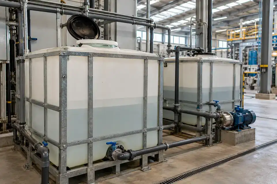
Keep day-tank replenishment aligned with production shifts. A local liquid-level reading gives operators a shared reference for water available to the next process, while historical readings help explain repeated refill cycles. Specify the working band, reserve level and reporting needs for the actual day tank rather than selecting the maximum family span by default.
- Measurements to observe
- Water level within the day tank’s operating band, plus refill and consumption patterns.
- Monitoring point
- The day tank supplying the selected production line or process-water distribution point.
- Placement & installation
- Provide an approved probe suspension or guide and service access. Locate the sensing point clear of filling splash and protect the cable along the full route.
- Project details
- Usable depth, water temperature, refill cycle, required low-level response and connection to the chosen platform.
Treated service-water storage
Stored treated-water level and recovery after transfer or production demand.
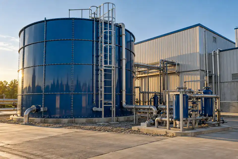
Monitor treated water after the plant’s treatment stage and before it is distributed to users. Comparing levels over time helps the utilities team understand storage recovery and demand during busy periods. Pair the readings with treatment and transfer-pump operating records when reviewing performance, and select probe and cable materials for the actual treated-water chemistry.
- Measurements to observe
- Stored treated-water level and recovery after transfer or production demand.
- Monitoring point
- The service-water holding tank downstream of the specified treatment stage.
- Placement & installation
- Use a stable, accessible immersion point with an agreed zero reference. Confirm water chemistry, temperature and cleaning practice before specifying the wetted assembly.
- Project details
- Treatment type, tank dimensions, working levels, water composition, cable route and reporting requirements.
Gravity-fed service-water tanks
Liquid level in the gravity tank and the available operating band above the outlet.
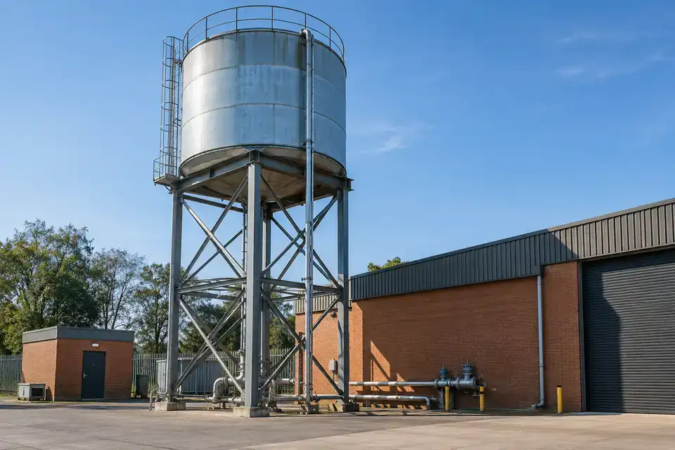
Follow the available head in a vented gravity-fed service tank. The water level can help operators plan a refill and understand a decline in supply to the served area. Connect the measurement to the tank’s own reference elevation and operating band, so readings from different tanks remain meaningful to the team reviewing them.
- Measurements to observe
- Liquid level in the gravity tank and the available operating band above the outlet.
- Monitoring point
- The vented service tank feeding the relevant building or industrial service area.
- Placement & installation
- Confirm tank access, cable support and the approved terminal location. Account for the probe position and tank datum when commissioning the displayed level.
- Project details
- Tank elevation, outlet level, refill arrangement, liquid suitability and the required reserve notification.
Emergency water-reserve monitoring
Reserve-water level and changes between planned inspections.
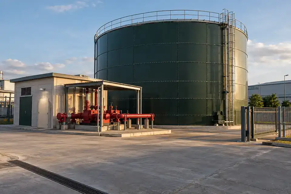
Maintain visibility of a water reserve that may be checked less frequently than production storage. Level trends support routine inspections, replenishment planning and investigation of an unexplained fall. Include the reading in the site’s reserve-management procedure, with the required alert recipients and response time agreed by those responsible for the installation.
- Measurements to observe
- Reserve-water level and changes between planned inspections.
- Monitoring point
- The designated reserve tank or compartment, using its documented operating levels.
- Placement & installation
- Select a serviceable immersion point and protect the cable and terminal from mechanical damage. Specify any approval or independent protection requirements in the project brief.
- Project details
- Reserve purpose, usable depth, permitted installation work, required approvals and notification / inspection workflow.
02Cooling & plant utilities5 monitoring tasks +
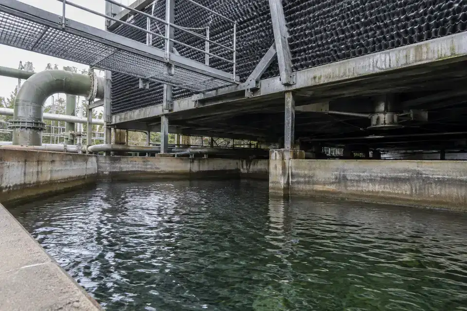
Keep utility-water storage visible through changing loads and seasons. Identify the actual tank, liquid treatment and temperature before selecting the probe, span and reporting profile.
Cooling-tower basin levels
Cooling-basin water height and refill / drawdown patterns.
Track the water held in a cooling-tower basin through changes in load, evaporation and make-up supply. A level history helps the maintenance team review recurring replenishment issues and schedule inspections. Select the sensing point and wetted assembly around circulating-water treatment, basin turbulence and the practical access available during normal maintenance.
- Measurements to observe
- Cooling-basin water height and refill / drawdown patterns.
- Monitoring point
- A representative basin compartment away from the strongest return flow and pump intake.
- Placement & installation
- Use the approved probe guide or support to maintain a repeatable position. Assess treatment chemicals, temperature, debris and cleaning access for the supplied assembly.
- Project details
- Basin depth, circulating-water chemistry, working temperature, maintenance access and required reporting profile.
Chilled-water make-up tanks
Liquid level and replenishment frequency in the make-up storage tank.
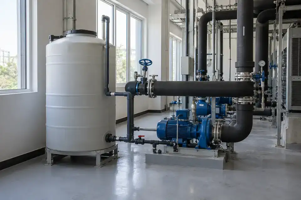
Observe the reserve in a make-up tank serving a chilled-water installation. Monitoring this storage point helps the utilities team review replenishment demand and arrange attention before the selected reserve level is reached. Define the tank being measured and its pressure conditions clearly, particularly where it sits beside a separate pressurized cooling circuit.
- Measurements to observe
- Liquid level and replenishment frequency in the make-up storage tank.
- Monitoring point
- The identified vented make-up or buffer tank, with its own level datum.
- Placement & installation
- Confirm the tank pressure condition, liquid treatment and accessible probe position. Keep the cable clear of pumps and equipment-service routes.
- Project details
- Tank type, usable depth, water treatment, room layout, pressure condition and expected replenishment cycle.
Evaporative-cooling supply tanks
Supply-water level and replenishment trends during evaporative-cooling operation.
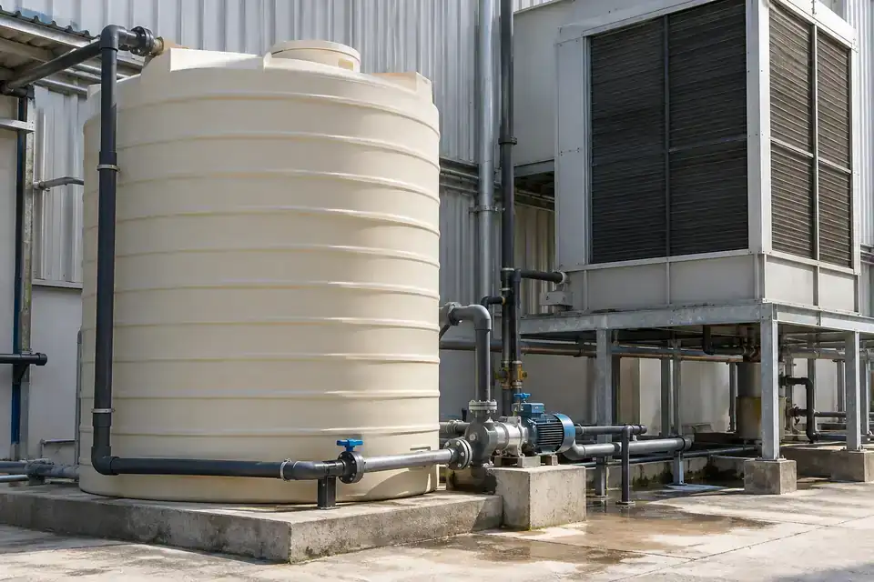
Monitor the supply tank feeding evaporative cooling equipment used around production or ventilation systems. Water-level trends help the team review supply interruptions, refill cycles and seasonal operating changes. Match the configured span to this local tank, and agree how a low-level notification will be acted on alongside the cooling equipment’s existing operating controls.
- Measurements to observe
- Supply-water level and replenishment trends during evaporative-cooling operation.
- Monitoring point
- The dedicated water supply or circulation tank serving the selected cooling unit.
- Placement & installation
- Choose a quiet, accessible immersion point clear of the return jet. Confirm water treatment, liquid temperature and cable protection for the equipment layout.
- Project details
- Cooling arrangement, tank dimensions, operating seasons, water chemistry and required notification recipients.
Boiler-feed pretreatment storage
Water level in the defined pretreatment or make-up storage tank.
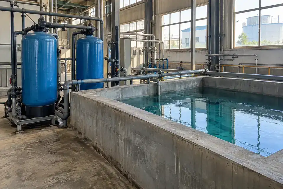
Keep a record of water available upstream of boiler-feed processing. This task concerns an identified pretreatment or make-up storage tank, where a level trend can support replenishment planning and shift handover. Specify the actual water temperature, pressure condition and cleaning regime so the supplied probe assembly is selected for that storage duty.
- Measurements to observe
- Water level in the defined pretreatment or make-up storage tank.
- Monitoring point
- An accessible storage stage before the boiler-feed or steam equipment, as specified by the plant.
- Placement & installation
- Confirm the selected liquid temperature and vessel pressure against the supplied configuration. Plan access and cable routing independently of hot equipment and steam lines.
- Project details
- Storage-stage drawing, normal / maximum temperature, pressure condition, water treatment and required level span.
Industrial humidification water supply
Water level in the humidification supply tank and changes during operating hours.
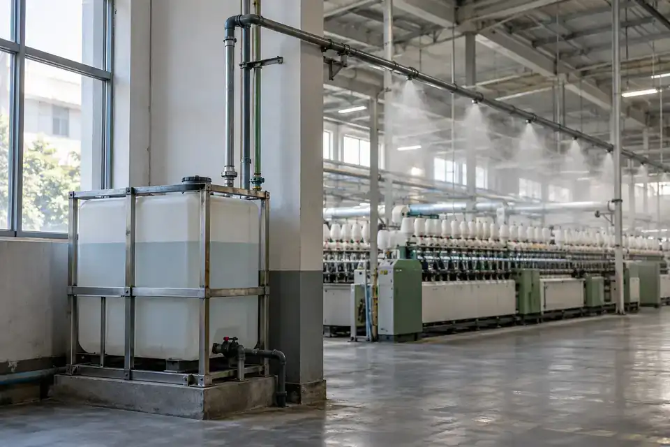
Monitor the water reserve serving industrial humidification equipment in a production or storage area. The readings help facilities staff review replenishment and associate supply changes with the system’s operating schedule. Identify the specific supply tank, its water quality requirements and service access before deciding on probe placement and the wireless reporting profile.
- Measurements to observe
- Water level in the humidification supply tank and changes during operating hours.
- Monitoring point
- The dedicated utility-water tank feeding the selected humidification system.
- Placement & installation
- Confirm the wetted assembly, cleaning method and expected water temperature. Position the terminal where maintenance access and radio coverage are both practical.
- Project details
- Humidification system type, tank depth, water treatment, cleaning schedule and platform destination.
03Manufacturing process water5 monitoring tasks +
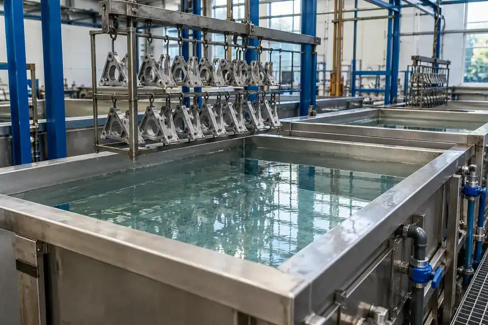
Bring process-water levels into shift handover and replenishment planning. Specify the exact liquid and handling conditions at each stage so the configuration fits the selected production duty.
Metal-component rinse tanks
Rinse-water level and refill patterns for the selected component-processing stage.
Follow the available water in a metal-component rinsing stage between production batches. A level trend supports refill planning and helps operators review changing use across shifts. Identify the exact rinse chemistry and temperature, including contamination carried in from the previous process, then select the probe and cable around that defined liquid.
- Measurements to observe
- Rinse-water level and refill patterns for the selected component-processing stage.
- Monitoring point
- A defined rinse tank or its water-supply buffer, separated from other process baths.
- Placement & installation
- Plan probe placement around part handling and tank cleaning. Confirm compatibility with the actual rinse liquid and maintain service access without obstructing production.
- Project details
- Rinse composition, carryover substances, temperature, tank geometry, moving-part clearance and usable depth.
Parts-washer rinse-water tanks
Liquid level in the designated rinse-water tank across wash cycles.
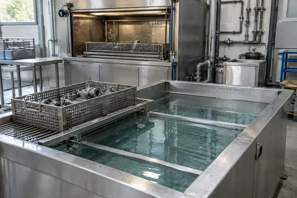
Observe the rinse-water tank associated with a parts-washing system. A time-stamped level record helps maintenance and production teams compare refill events with operating cycles and investigate unusual consumption. Specify the rinse stage separately from detergents or other baths, and include the cleaning and service conditions in the proposed sensor configuration.
- Measurements to observe
- Liquid level in the designated rinse-water tank across wash cycles.
- Monitoring point
- The rinse reservoir or clean-water buffer serving the selected parts washer.
- Placement & installation
- Locate the probe clear of circulating parts and pump suction. Confirm liquid compatibility, temperature and the permitted installation arrangement with the equipment owner.
- Project details
- Washer layout, identified liquid, cycle duration, working temperature, access and reporting needs.
Textile process-water buffer tanks
Liquid level in the specified textile-process water buffer.
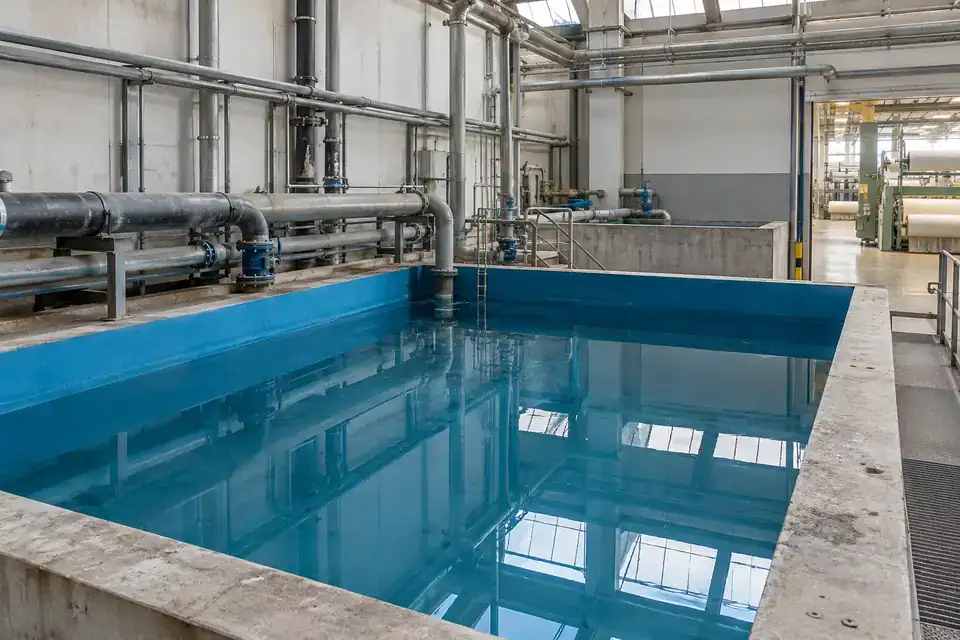
Monitor a process-water buffer that supports textile production. Level history helps utilities staff review replenishment demand between batches and plan attention to storage before a selected operating threshold is reached. Define whether the point holds incoming water, conditioned water or a process mixture, since each requires its own compatibility and temperature assessment.
- Measurements to observe
- Liquid level in the specified textile-process water buffer.
- Monitoring point
- The selected water-storage or buffer stage serving the textile production area.
- Placement & installation
- Confirm the liquid and temperature at this point. Place the probe away from filling jets and moving equipment, with protected cable routing and access for inspection.
- Project details
- Water / mixture identity, batch pattern, tank dimensions, temperature, cleaning conditions and desired notifications.
Surface-treatment rinse-water storage
Liquid level in the nominated rinse-water tank or replenishment reservoir.
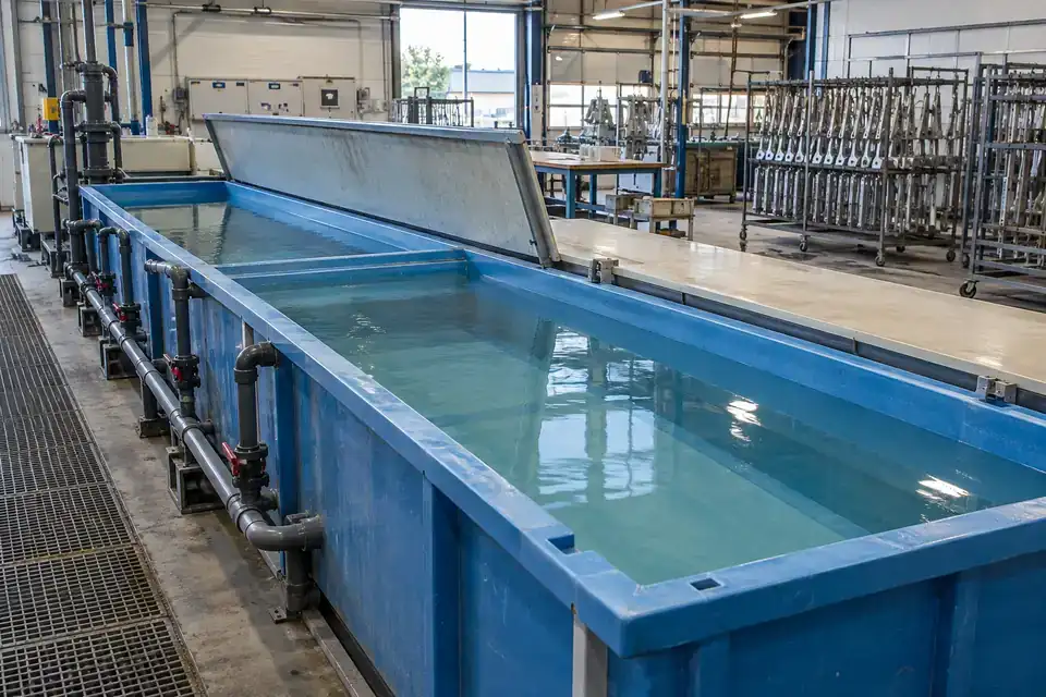
Keep the selected rinse-water storage stage visible to the surface-treatment team. Readings can support replenishment planning and a review of water use across operating shifts. Specify the exact rinse solution, carryover chemicals and service temperature; a suitable assembly is selected for that point, with the associated cleaning and handling requirements included.
- Measurements to observe
- Liquid level in the nominated rinse-water tank or replenishment reservoir.
- Monitoring point
- A clearly identified rinse stage on the surface-treatment line.
- Placement & installation
- Provide approved cable support and clearance from hoists and workpieces. Confirm the wetted materials and cable suitability for the specified rinse composition and maintenance method.
- Project details
- Rinse chemistry, possible carryover, working temperature, tank depth, handling clearance and cleaning routine.
Ceramic-plant clarified-water tanks
Clarified-water level in the reuse or process-supply tank.
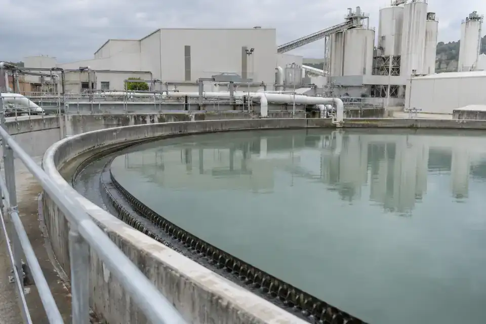
Observe clarified water stored for reuse in ceramic production. A level trend helps the utilities team compare recovery with demand and arrange replenishment at the chosen operating threshold. Describe residual solids and settling behaviour so the installation can be planned for a stable liquid-level reference and accessible inspection of the probe assembly.
- Measurements to observe
- Clarified-water level in the reuse or process-supply tank.
- Monitoring point
- The liquid storage section downstream of the defined settling or clarification stage.
- Placement & installation
- Position the probe clear of settled material and the inlet stream, using approved support. Include residual solids, abrasion and cleaning access in the configuration review.
- Project details
- Clarification stage, residual-solids conditions, tank depth, water temperature, access and operating band.
04Industrial effluent & recovery5 monitoring tasks +
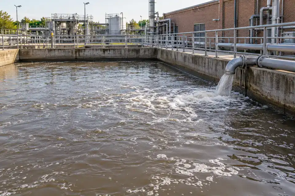
Follow collection, treatment and reuse with time-stamped liquid levels. Match the assembly to the actual effluent, deposits, mixing conditions and practical maintenance access.
Factory effluent equalization tanks
Liquid level and accumulation / transfer trends in the equalization stage.
Follow incoming liquid accumulation in an effluent equalization tank before it enters the next treatment stage. Level history helps the treatment team compare collection and transfer patterns across production shifts. Select the assembly for the actual wastewater composition and maintenance conditions, and agree the reporting and high-level notification needs for this particular tank.
- Measurements to observe
- Liquid level and accumulation / transfer trends in the equalization stage.
- Monitoring point
- A representative liquid area of the equalization tank with a documented reference datum.
- Placement & installation
- Plan the sensing point around agitators, inlet turbulence and settled material. Confirm liquid compatibility, cable protection and safe retrieval for cleaning.
- Project details
- Effluent composition, temperature, tank geometry, agitation, expected deposits and required level response.
Neutralization-stage collection tanks
Liquid height and collection trends in the specified neutralization-stage tank.
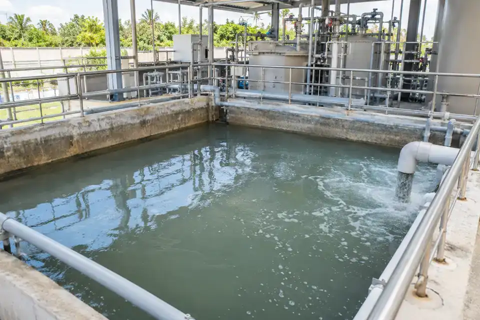
Monitor liquid collected at an identified neutralization-treatment stage. The trend provides a common reference for operators reviewing accumulation and onward transfer. The required probe and cable depend on the actual mixture, its concentration range and cleaning conditions, so provide those details alongside the level span and installation drawing when requesting a configuration.
- Measurements to observe
- Liquid height and collection trends in the specified neutralization-stage tank.
- Monitoring point
- The designated collection or holding compartment within the treatment arrangement.
- Placement & installation
- Confirm medium compatibility across the expected composition and temperature range. Plan a retrievable installation clear of mixing equipment and dosing-entry turbulence.
- Project details
- Mixture identity and concentration, temperature, mixing arrangement, cleaning chemicals, depth and any area-classification requirements.
Treated-effluent holding tanks
Treated-liquid level and changes between storage, transfer or reuse events.
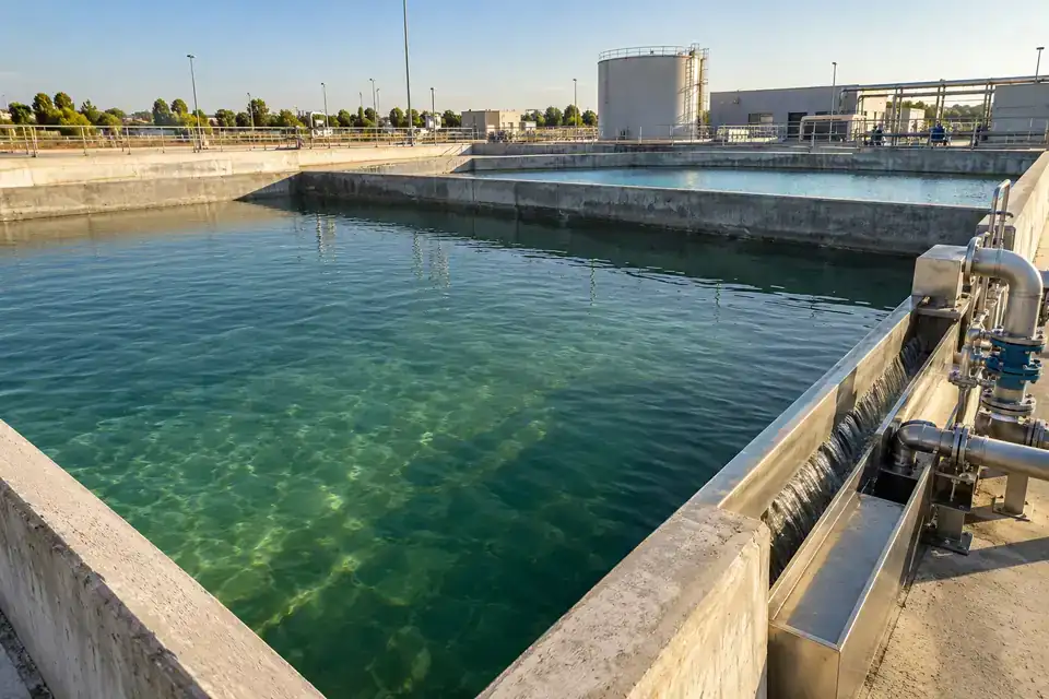
Observe treated effluent held before reuse, transfer or discharge under the site’s operating procedure. Time-stamped levels help staff review storage recovery and plan attention to the selected operating band. Include the remaining liquid constituents, expected deposits and service access in the configuration so the measurement point suits this final holding stage.
- Measurements to observe
- Treated-liquid level and changes between storage, transfer or reuse events.
- Monitoring point
- The final holding tank or a defined treated-effluent storage compartment.
- Placement & installation
- Select a stable immersion point clear of inlet and outlet disturbances. Confirm liquid suitability and make the cable route and probe retrieval accessible for routine service.
- Project details
- Treatment stage, liquid composition, tank dimensions, discharge / reuse workflow and required reporting intervals.
Sludge-supernatant collection
Separated-liquid level in the supernatant collection tank.
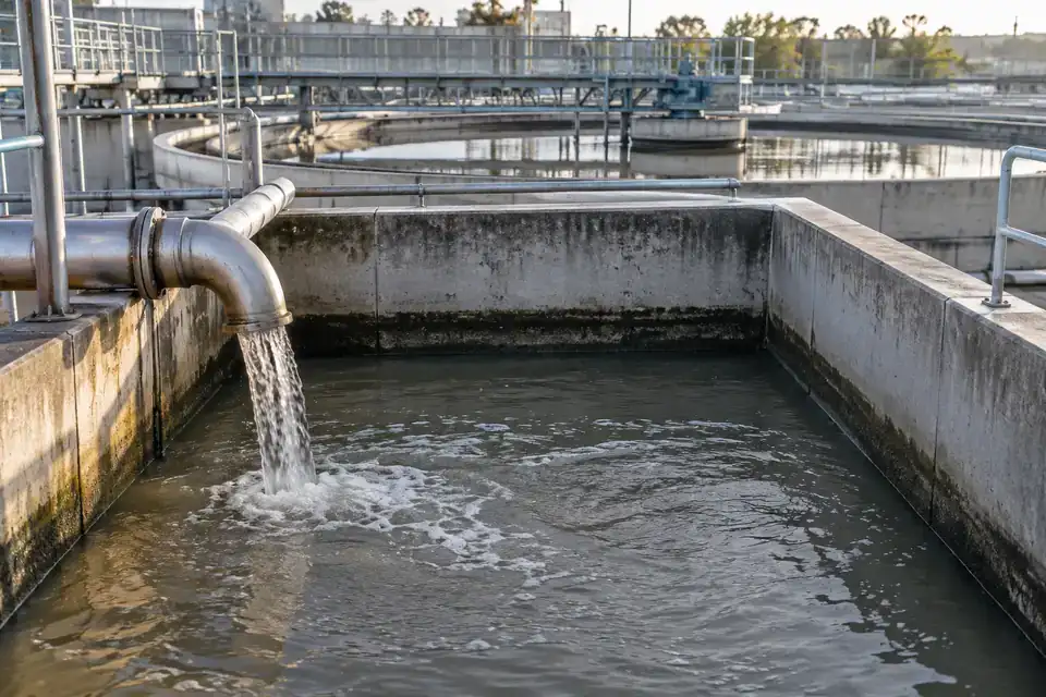
Track the separated liquid collected from a sludge-handling process. This monitoring task focuses on the supernatant-water level in its receiving tank, giving operators a reference for return or transfer planning. Identify residual solids and the collection arrangement so the probe position and inspection routine are selected around the liquid being measured.
- Measurements to observe
- Separated-liquid level in the supernatant collection tank.
- Monitoring point
- The identified liquid receiving compartment downstream of sludge separation.
- Placement & installation
- Assess residual solids and fouling before choosing the assembly. Keep the probe above accumulated deposits with approved support and practical access for inspection.
- Project details
- Separation process, residual-solids conditions, receiving-tank depth, return cycle, cleaning access and liquid temperature.
Healthcare wastewater collection
Collected-wastewater level and transfer trends in the nominated receiving tank.
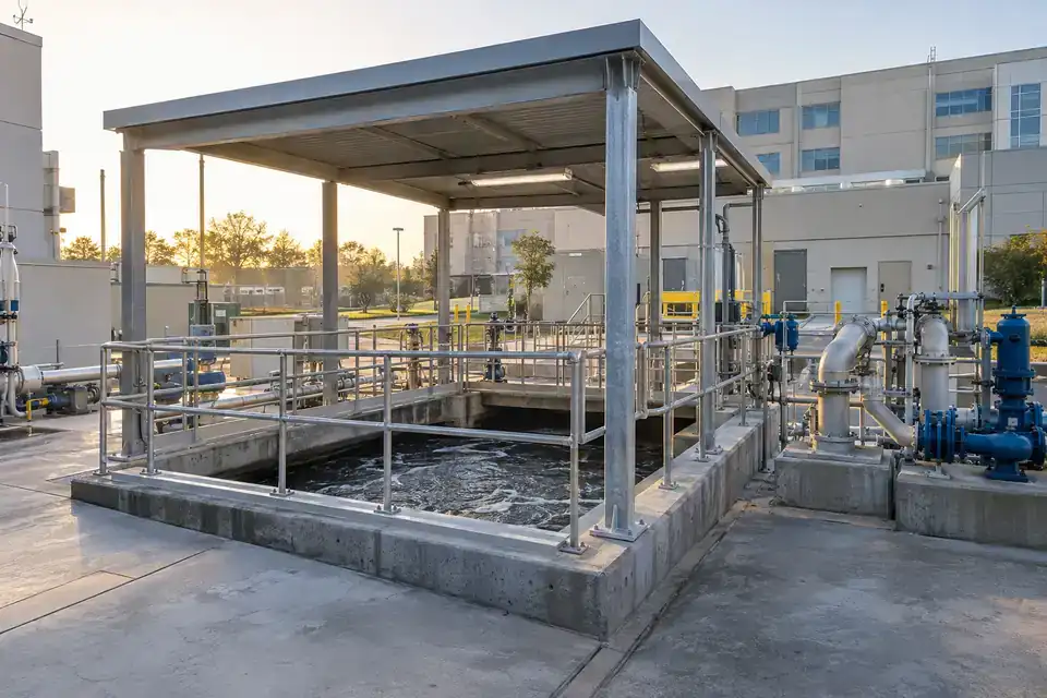
Monitor wastewater collected before a healthcare facility’s specified treatment stage. Level history can help facilities staff plan inspections and review collection versus transfer through the day. Confirm the exact wastewater composition, disinfection and cleaning practices with the site team, then select a configuration and installation procedure appropriate to that collection point.
- Measurements to observe
- Collected-wastewater level and transfer trends in the nominated receiving tank.
- Monitoring point
- The designated wastewater holding or collection stage in the facility’s treatment system.
- Placement & installation
- Plan protected cable routing and retrieval using the facility’s approved access procedure. Confirm liquid and cleaning compatibility along with any required installation approvals.
- Project details
- Wastewater composition, disinfectants, temperature, tank depth, site-access conditions and notification workflow.
05Drainage sumps & pump stations5 monitoring tasks +
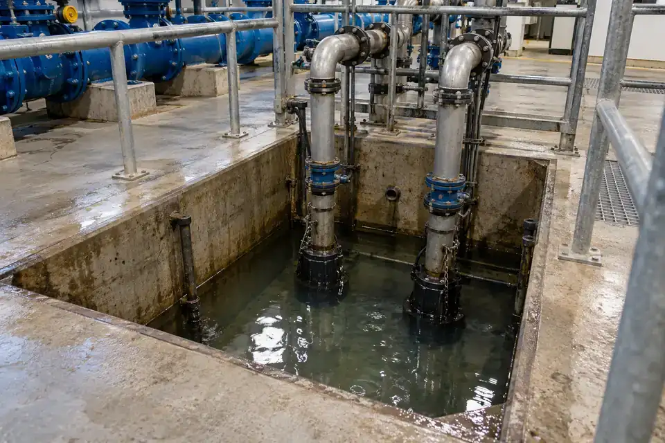
See water accumulating at distributed sumps and collection points. Agree the operating band, notification timing and service access around each local drainage task.
Plant-room drainage sumps
Collection level and drawdown relative to the sump's operating marks.
Record rising and falling water levels in plant-room sumps that collect seepage, condensate drains or utility leakage. A documented sensing point helps the maintenance team compare normal collection with unusual accumulation and plan an inspection before the pit reaches its operating limit. Review the inflow pattern, drainage arrangement and alert timing together, then select the probe position and reporting profile around the actual sump.
- Measurements to observe
- Collection level and drawdown relative to the sump's operating marks.
- Monitoring point
- An accessible, representative part of the pit away from the main inlet and pump intake.
- Placement & installation
- Provide stable probe support, cable protection and inspection access. Mount the wireless terminal above the expected water level and verify reception in the plant room.
- Project details
- Sump section, liquid sources, operating levels, pump arrangement, temperature, inspection access, coverage and required alert timing.
Factory washdown collection
Level buildup during washdown and reduction after transfer or removal.
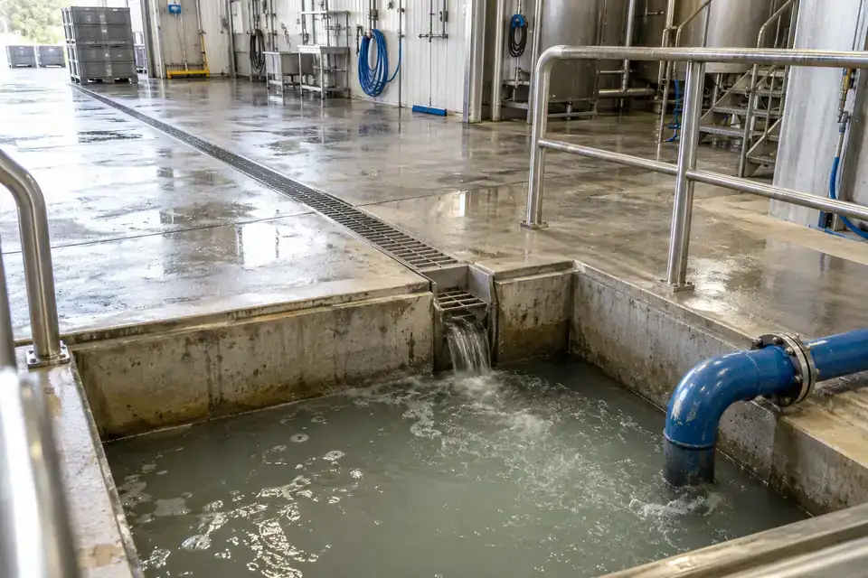
Observe collection levels as factory washdown water passes from floor drains into a holding pit or tank. Comparing the level trend with cleaning schedules helps the team review collection capacity and the timing of removal or transfer. Specify the detergents, process residues and solids present so probe and cable selection fits the liquid. Define practical alert levels around the tank's working volume and operating routine.
- Measurements to observe
- Level buildup during washdown and reduction after transfer or removal.
- Monitoring point
- A representative collection compartment downstream of the drain entry, with a defined level reference.
- Placement & installation
- Route the cable clear of cleaning equipment and provide access for residue inspection. Review the probe position, protection and wireless terminal location with the cleaning layout.
- Project details
- Cleaning schedule, detergent and residue details, solids, collection depth, transfer arrangement, temperature and notification workflow.
Factory stormwater lift stations
Wet-well level during storm inflow and subsequent drainage.
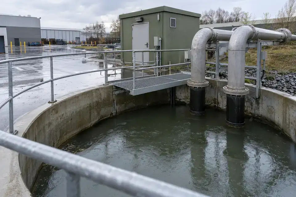
Track water collection and drawdown at a factory stormwater lift station during rainfall and the period afterward. The level record gives site operators context for drainage inspections, pump-operation review and unusual accumulation. Match the reporting profile to the expected speed of change, then agree thresholds and recipients with the drainage team. Include sediment, debris, seasonal water levels and the separate pump-control arrangement in the project brief.
- Measurements to observe
- Wet-well level during storm inflow and subsequent drainage.
- Monitoring point
- The wet well at a stable position outside the strongest inlet jet and pump suction zone.
- Placement & installation
- Plan probe support and access for debris inspection. Keep the terminal accessible above the expected water line and confirm coverage at the lift station.
- Project details
- Catchment and wet-well layout, level marks, inflow changes, debris, pump controller, coverage, reporting and response requirements.
Underground lift-pit monitoring
Standing-water level and the trend between drainage cycles.
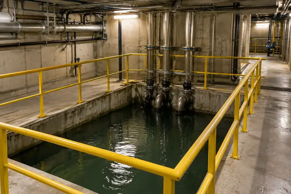
Follow water accumulation in an underground lift pit serving industrial parking, service access or below-grade utility areas. A consistent level reference helps maintenance staff compare routine seepage with a changing drainage pattern between visits. Plan alerts around the pit's usable depth and the team's inspection workflow. Review access, sediment, cable routing and radio reception before selecting the installation, with pump automation defined through the site's controller.
- Measurements to observe
- Standing-water level and the trend between drainage cycles.
- Monitoring point
- The accessible collection pit at a position clear of moving equipment and strong suction.
- Placement & installation
- Protect probe and cable from service work and document the reference depth. Evaluate an accessible terminal position with a verified wireless path from the below-grade site.
- Project details
- Pit drawing, maximum level, seepage sources, service access, pump system, terminal location and notification timing.
Industrial containment collection
Collected-liquid level relative to the tank's defined handling and inspection marks.
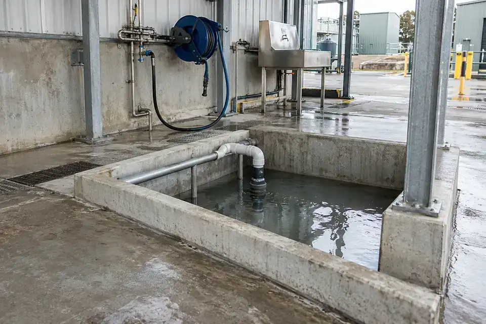
Give the operating team a level record from a containment collection tank where the collected liquid is identified and its conditions are known. Review accumulation against inspection and removal records to support the site's handling plan. Share the liquid composition, cleaning method and possible changes in content so a matching probe and cable can be evaluated. Select the range and alert profile around the collection arrangement.
- Measurements to observe
- Collected-liquid level relative to the tank's defined handling and inspection marks.
- Monitoring point
- A designated collection compartment with known liquid conditions and access for assessment.
- Placement & installation
- Agree the wetted configuration, stable probe support and cable route for the specified contents. Include site classification and service access in the installation review.
- Project details
- Collected liquid and concentration, potential variation, tank depth, temperature, pressure, cleaning, site requirements and handling workflow.
06Water systems by industry5 monitoring tasks +
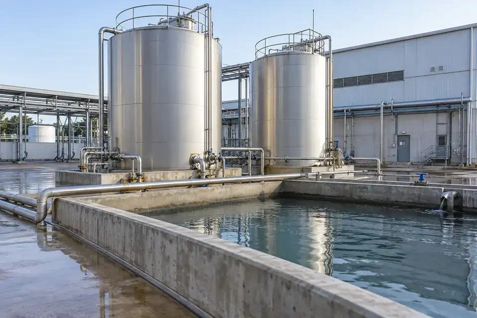
Use a clear level reference across industry-specific utility and water-recovery systems. Define the actual storage duty, liquid constituents and site requirements for each configuration.
Food & beverage utility-water storage
Service-water storage level through utility demand and replenishment cycles.
Observe the level of service-water reserves used by utilities in a food or beverage facility. The trend adds context to replenishment planning and maintenance checks across shifts, particularly where several tanks supply separate plant services. Define the utility function and the water's contact designation in the project brief so the required documentation and wetted configuration can be reviewed. Set alert levels around the site's operating reserve.
- Measurements to observe
- Service-water storage level through utility demand and replenishment cycles.
- Monitoring point
- A clearly identified utility-water tank with documented function, level marks and liquid conditions.
- Placement & installation
- Plan probe positioning and cable routing around tank access and cleaning. Mount the communication terminal for inspection and confirm the water-contact requirements for the actual application.
- Project details
- Utility purpose, water specification and contact requirements, storage depth, temperature, cleaning method, network and reporting profile.
Pharmaceutical utility-water systems
Utility-water reserve level and replenishment trends at a designated plant-service tank.
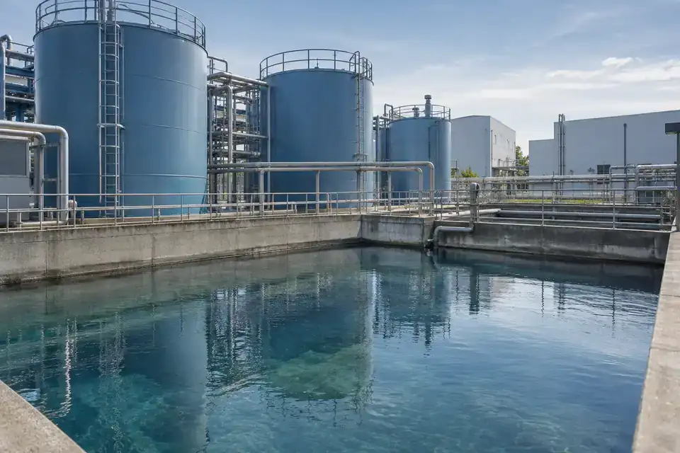
Track service-water levels in a pharmaceutical site's plant utilities, with the water system and monitoring purpose clearly identified. A defined record supports routine reserve checks and coordination between utility operators and maintenance staff. Specify the tank function, water designation, temperature and cleaning practice so the configuration and required evidence can be reviewed. Keep level thresholds, data ownership and the reporting schedule aligned with the site's documented workflow.
- Measurements to observe
- Utility-water reserve level and replenishment trends at a designated plant-service tank.
- Monitoring point
- A service-water storage point whose use and operating conditions are defined by the facility.
- Placement & installation
- Coordinate probe and terminal placement with utility access and tank cleaning. Specify any contact, documentation or site requirements with the exact supplied configuration.
- Project details
- Water-system designation, tank function, depth, temperature, pressure, cleaning, documentation requirements, platform and utility workflow.
Paper-mill water-recovery tanks
Recovery-water holding level during incoming collection and transfer to reuse.
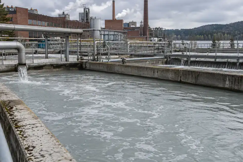
Follow liquid levels in a paper mill's recovery-water tanks to review how storage changes with production and transfer schedules. Use the record alongside process logs to identify tanks that merit inspection or replenishment attention. Characterize the monitored water stream, including fibers, suspended solids, chemistry and temperature, before choosing the probe arrangement. A serviceable sensing position and clear level reference make comparisons between operating periods more useful.
- Measurements to observe
- Recovery-water holding level during incoming collection and transfer to reuse.
- Monitoring point
- An agreed water compartment, with fiber and sediment conditions documented for probe selection.
- Placement & installation
- Provide access for sensing-surface inspection and route cables clear of transfer equipment. Review turbulence, fouling and probe support around the chosen compartment.
- Project details
- Recovery stream, fiber and solids content, chemistry, temperature, tank geometry, transfers, cleaning and required monitoring timing.
Concrete-plant recycled-water collection
Collection or clarified-water level at the selected recycling stage.
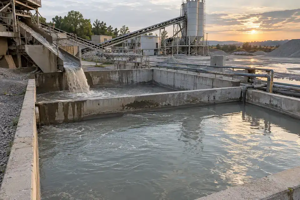
Observe water levels in the collection and clarified-water sections of a concrete plant's recycling arrangement. Comparing the trend with washout and reuse schedules helps the team review available water and plan inspections. Select a sensing compartment after characterizing sediment, alkalinity and remaining solids, then agree probe access and cleaning. The installation should represent the monitored water stage and keep its reference consistent through routine plant operations.
- Measurements to observe
- Collection or clarified-water level at the selected recycling stage.
- Monitoring point
- A designated water compartment with settling behavior and residual solids assessed for the installation.
- Placement & installation
- Position the probe with access for sediment and fouling checks. Protect the cable from loaders and washout work, and verify the terminal's reception at the water area.
- Project details
- Recycling-stage layout, alkalinity, solids and settling pattern, maximum level, cleaning, equipment movements, platform and reporting.
Recycling-plant wash-water tanks
Wash-water reserve or collection level during washing, recovery and replenishment.
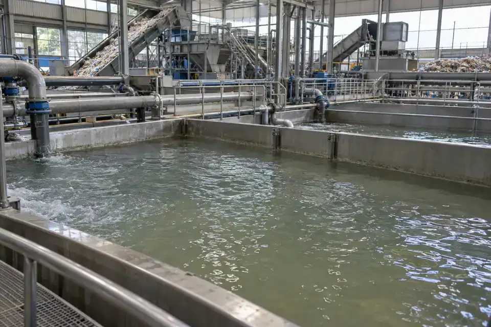
Record wash-water storage and collection levels at a recycling plant as material washing and transfer cycles change throughout the shift. The trend supports a review of replenishment timing and collection capacity alongside production records. Specify the washed materials, detergents and suspended contaminants so the liquid and fouling conditions are understood. Choose a maintainable probe position and reporting profile around the particular tank's role in the washing arrangement.
- Measurements to observe
- Wash-water reserve or collection level during washing, recovery and replenishment.
- Monitoring point
- A designated tank compartment with the wash-water composition and solids characterized.
- Placement & installation
- Provide probe support and inspection access around transfer pipework. Protect the cable from moving materials and include cleaning practice in the configuration review.
- Project details
- Material stream, detergents, contaminants, solids, temperature, tank depth, washing cycles, cleaning and expected data timing.
07Resources & underground dewatering5 monitoring tasks +
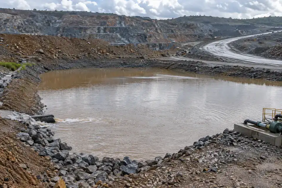
Follow changing water levels at collection basins, drainage sumps and wells. Choose the reference point, cable route and terminal position around depth, access and site conditions.
Mine dewatering collection
Collection-water level relative to the mine site's defined reference and operating marks.
Follow water levels at a mine dewatering collection point to give operators a documented trend between site inspections. Compare inflow and drawdown periods with the pumping record and changing work areas. Define the liquid, sediment, maximum level and access arrangements before selecting the sensing position. Include site classification, equipment requirements and the communication route in the project so the proposed configuration fits the designated collection location.
- Measurements to observe
- Collection-water level relative to the mine site's defined reference and operating marks.
- Monitoring point
- An approved collection sump or water compartment with sediment and inflow conditions recorded.
- Placement & installation
- Plan a serviceable probe position and protected cable route with the site team. Confirm terminal placement, coverage and all location-specific equipment requirements.
- Project details
- Collection layout, water composition, sediment, reference depth, site classification, access, pump controller and reporting requirements.
Quarry settling-water basins
Water level at an identified basin reference through collection and transfer periods.
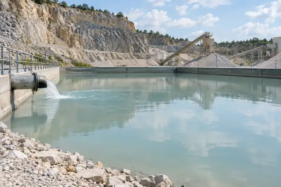
Observe water-level changes in a quarry settling basin as drainage enters and water is transferred for reuse or treatment. A defined reference supports comparisons across rain events and production periods. Choose the monitored water zone after reviewing sediment depth, suspended material and access for inspection. Position and service arrangements should follow the basin's changing settling pattern so the record remains useful for the operator's water-management review.
- Measurements to observe
- Water level at an identified basin reference through collection and transfer periods.
- Monitoring point
- A stable, accessible water zone selected with the sediment profile and transfer arrangement.
- Placement & installation
- Provide protected probe support and cable routing clear of earthmoving work. Include an inspection method for changes in sediment and review terminal placement at the basin edge.
- Project details
- Basin section, sediment profile, water composition, depth range, equipment access, transfer schedule, coverage and reporting.
Construction dewatering wells
Water-level elevation or depth relative to the agreed well datum.
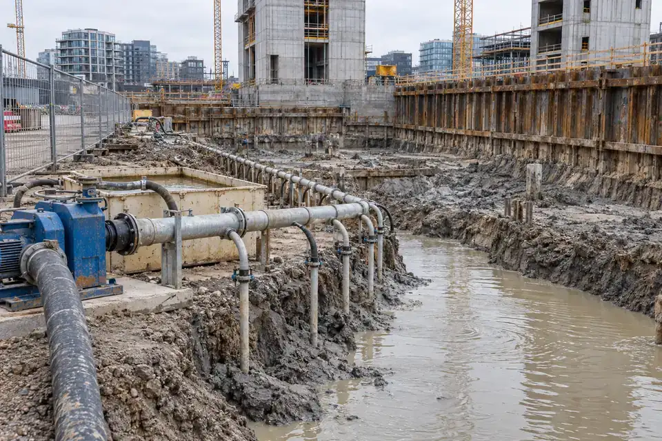
Track the water level in a construction dewatering well against a documented site datum and pumping schedule. The record gives the project team context for inspections and changes during excavation work. Specify the well diameter, depth, expected level range and sediment conditions so the probe and cable arrangement can be reviewed. Keep each well identified and compare readings with the site's reference checks and current construction stage.
- Measurements to observe
- Water-level elevation or depth relative to the agreed well datum.
- Monitoring point
- An identified well with a recorded casing reference, probe position and pumping arrangement.
- Placement & installation
- Keep the probe and cable clear of pumping equipment and protect the route at the wellhead. Document the installed reference and provide access for level checks.
- Project details
- Well diameter and depth, datum, level range, pumping layout, sediment, construction access, point identifiers and reporting schedule.
Tunnel drainage sumps
Drainage collection level and drawdown between pumping periods.
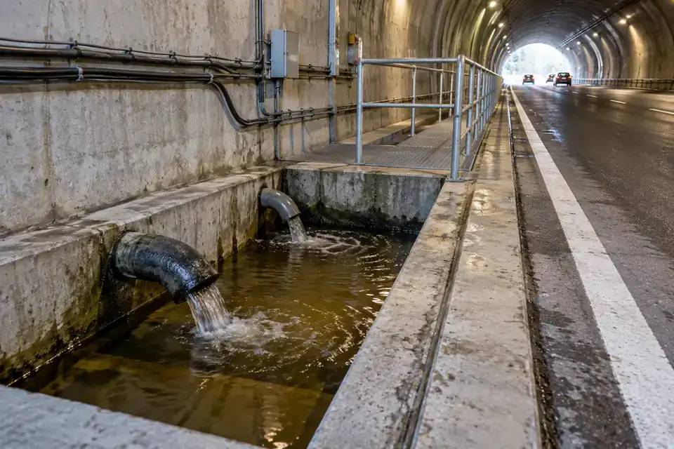
Follow collection levels in tunnel drainage sumps that gather seepage and water from the drainage channel. Reviewing the trend beside pumping and maintenance records helps the team identify changes that merit a site check. Select the sensing point around the sump geometry, inlet movement and solids, then plan protected cable routing and accessible terminal mounting. Verify the reporting path at the actual underground location during commissioning.
- Measurements to observe
- Drainage collection level and drawdown between pumping periods.
- Monitoring point
- A documented sump compartment away from the strongest inflow and accessible under the site's maintenance plan.
- Placement & installation
- Coordinate probe support, cable protection and terminal location with tunnel services. Confirm access conditions, radio reception and any gateway path for the selected deployment.
- Project details
- Tunnel and sump section, water and solids, reference level, access restrictions, site requirements, pumping record and communication route.
Industrial groundwater wells
Groundwater level relative to an identified well datum through the monitoring period.
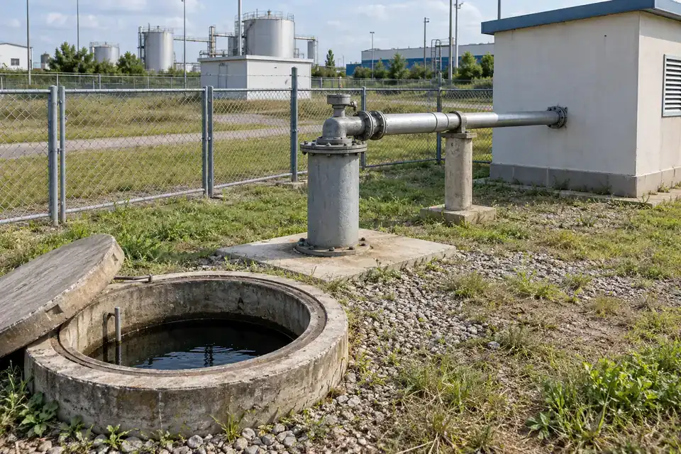
Build a consistent water-level record from groundwater wells serving an industrial site's monitoring plan. Identify each point and its datum so seasonal changes and drawdown periods can be compared with pumping and site records. Specify the well depth, liquid conditions and required tolerance, then select the probe position and cable length together. Periodic reference checks and documented installation details help the team interpret the resulting time series.
- Measurements to observe
- Groundwater level relative to an identified well datum through the monitoring period.
- Monitoring point
- A designated well with a known reference, depth and access arrangement.
- Placement & installation
- Protect the cable at the wellhead and maintain a consistent probe position. Confirm the selected range, liquid suitability, terminal mounting and method for reference checks.
- Project details
- Well register, diameter, depth, datum, water chemistry, temperature, pumping context, accuracy need, coverage and reporting.
08Source water & site resilience5 monitoring tasks +
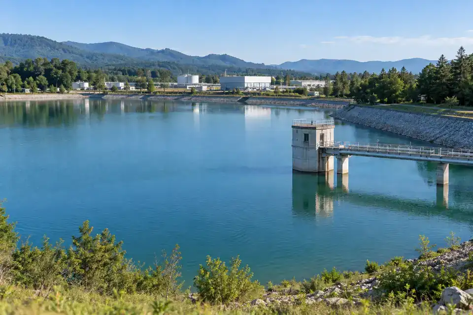
Extend level visibility to the water sources and retention areas supporting a site. Use a shared datum and reporting plan that makes readings useful alongside the site’s operating records.
Industrial raw-water reservoirs
Raw-water reserve level through inflow and plant withdrawal periods.
Follow reserve levels in an industrial raw-water reservoir as inflow, plant demand and weather change. The record supports replenishment planning and a review of usable storage alongside the site's water-supply schedule. Define the level reference, expected range and inlet conditions before choosing the probe location. Include seasonal sediment, water composition and maintenance access so the sensing arrangement and reporting profile match the reservoir's operating role.
- Measurements to observe
- Raw-water reserve level through inflow and plant withdrawal periods.
- Monitoring point
- A representative reservoir position with a defined datum, outside strong inlet or withdrawal turbulence.
- Placement & installation
- Plan stable probe support and a cable route suitable for water-level variation. Mount the terminal at an accessible position above the expected water line and check coverage.
- Project details
- Reservoir section and datum, level range, water conditions, inlet and outlet positions, sediment, access, platform and reporting.
River-intake water levels
River stage relative to the agreed intake monitoring datum.
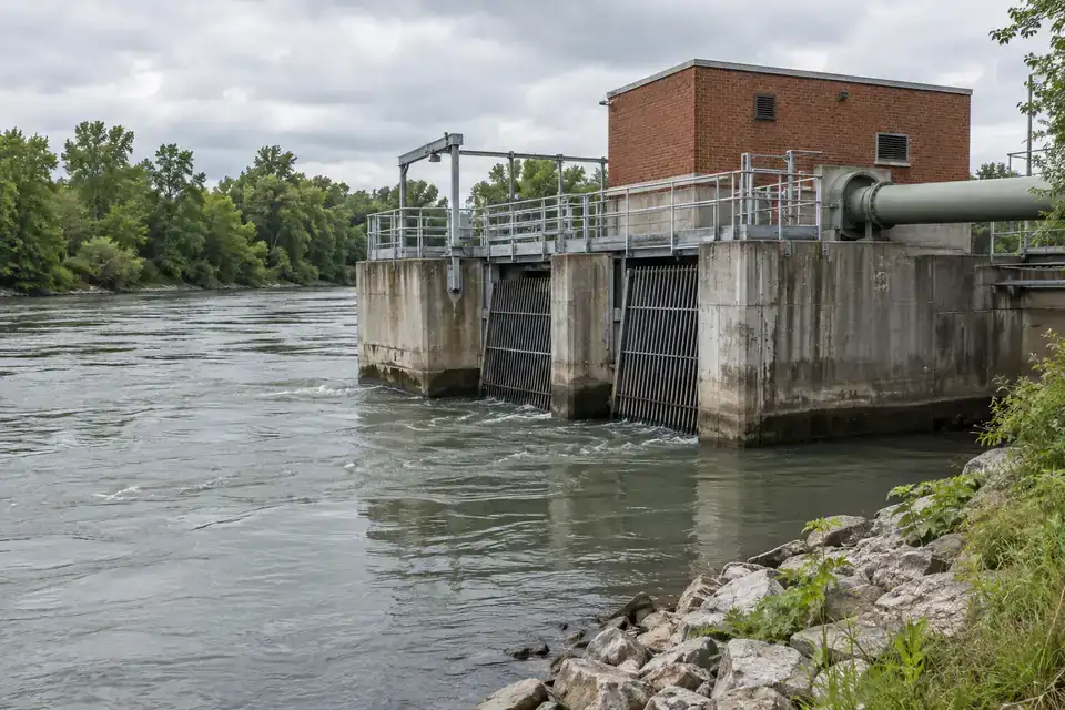
Observe river water levels near an industrial intake to add context to source-water availability and the operator's inspection plan. A documented sensing datum lets the team compare changing stage with intake operation and local observations. Choose a protected position after reviewing currents, debris, sediment and seasonal levels. Select the range, installation and reporting profile for the level task, with any flow assessment defined through the wider water-management design.
- Measurements to observe
- River stage relative to the agreed intake monitoring datum.
- Monitoring point
- A designated river-edge or intake-structure position with current and debris conditions reviewed.
- Placement & installation
- Provide stable support and protected cable routing for seasonal water changes. Keep the terminal accessible and verify the wireless path from the intake location.
- Project details
- Intake drawing, stage datum, seasonal range, current and debris, sediment, site access, accuracy need and reporting.
Irrigation and supply-canal levels
Canal water level at identified locations relative to their recorded datum.
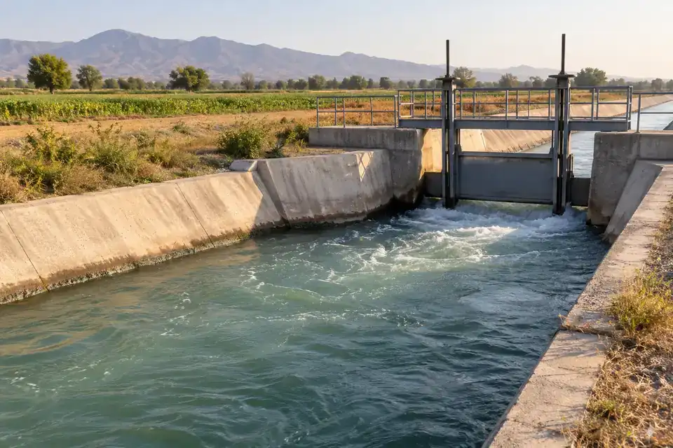
Record water levels at selected points in an irrigation or site-supply canal to support the team's review of delivery schedules and changing conditions. Keep each point's datum and position documented for meaningful comparisons. Review velocity, debris, sediment and access when selecting probe support. The level trend can be considered alongside gate settings and field observations, with any discharge calculation specified as a separate hydraulic assessment for the site.
- Measurements to observe
- Canal water level at identified locations relative to their recorded datum.
- Monitoring point
- A representative canal section selected with the delivery arrangement and local flow conditions.
- Placement & installation
- Plan protected probe support and cable routing clear of gate work and debris. Include seasonal level variation, inspection access and terminal reception in the deployment.
- Project details
- Canal section and datum, level range, gate operation, velocity, debris and sediment, access, coverage and reporting.
Remote service-water wells
Well water level through service-water withdrawal and recovery periods.
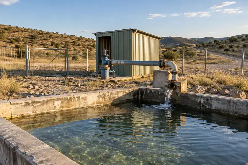
Track water levels in a remote well used for a site's service-water supply, giving operators a record between visits. Compare drawdown and recovery with the pumping schedule and demand pattern. Select the probe range, cable length and reference point around the well construction, then verify coverage at the terminal. Agree reporting frequency and the battery-life estimate for the site's monitoring objective and actual operating conditions.
- Measurements to observe
- Well water level through service-water withdrawal and recovery periods.
- Monitoring point
- An identified supply well with recorded construction, pumping position and reference datum.
- Placement & installation
- Protect the probe cable around the pump and wellhead, with access for checks. Position the terminal for reception and agree the power and reporting profile.
- Project details
- Well depth and diameter, datum, pump layout, water conditions, level range, coverage, visit frequency and reporting need.
Industrial stormwater-retention basins
Retention-basin level through rainfall collection and subsequent release.
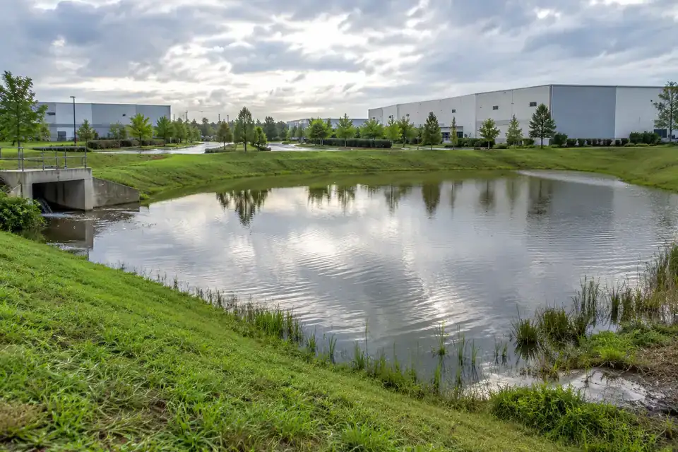
Follow water-level buildup and recession in an industrial stormwater-retention basin during and after rainfall. Reviewing the record with rainfall and outlet inspections helps the site team understand changing storage conditions. Set a defined datum and review the seasonal range, sediment and debris before selecting the sensing point. Where usable volume is needed, include the basin geometry in the platform calculation and agree the project's alert workflow.
- Measurements to observe
- Retention-basin level through rainfall collection and subsequent release.
- Monitoring point
- A documented basin position representing stored water, away from strong inlet turbulence.
- Placement & installation
- Use stable probe support and protected cable routing with inspection access. Confirm terminal placement above the expected water line and the wireless route for the site.
- Project details
- Basin section and datum, maximum level, sediment, inlet and outlet layout, volume mapping, coverage, reporting and alert recipients.
SERIES & CONFIGURATIONS
One series.
The level configuration your project needs.
H200, H300 and H500 are the published level sensor family. Select the range, probe cable and mounting, liquid and vessel conditions, wireless variant and reporting profile together. The quotation defines the supplied configuration and its installation requirements.
H200
Range and deployment configuration selected for your project
Discuss this configuration ↗H300
Range and deployment configuration selected for your project
Discuss this configuration ↗H500
Range and deployment configuration selected for your project
Discuss this configuration ↗| Published models | H200 / H300 / H500 |
|---|---|
| Sensor format | Submersible probe with cable and wireless communication terminal |
| Level range | 0–200 m, customizable; application-specific full scale selected for the required level and accuracy |
| Published accuracy | ±0.5% FS; higher precision customizable |
| Long-term stability | ±0.2% FS/year; a separate metric from measurement accuracy |
| Operating temperature | −20°C to +70°C published; confirm probe, liquid and cable limits for the supplied configuration |
| Storage temperature | −20°C to +80°C |
| Wireless options | 4G LTE / NB-IoT / LoRa, by supplied configuration |
| Data protocol & platform | MQTT listed; 4G/NB-IoT reporting to Hitelecom Cloud or a customer platform |
| Power | Internal battery; power arrangement specified with the supplied configuration |
| Battery-life reference | More than 10 years at four-hour reporting under specified test conditions; actual runtime depends on configuration and operating profile |
| Protection | IP68 enclosure listed; component immersion conditions confirmed for the project |
| Transmitter mounting | Mounting lugs / pole clamp / slotted mount, depending on configuration |
| Configuration & maintenance | NFC activation and local setup; remote OTA updates supported |
| Probe cable | Cable length can be adapted to the site; probe, cable and liquid compatibility reviewed during selection |
Bring the specification back to your project.
Define the level task
Application · Liquid · Maximum level · Required tolerance · Tank pressure · Operating temperature
Define the installation
Probe reference · Cable length and route · Terminal mounting · Fouling conditions · Inspection access
Define the data path
Wireless variant · Sampling and reporting · Receiving platform · Alert recipients · Controller integration
CONNECTIVITY & INTEGRATION
Hitelecom Cloud.
Your level data, connected.
The published 4G and NB-IoT deployment reports via MQTT to Hitelecom Cloud or a customer platform. Agree the endpoint, authentication and message format with the supplied configuration. For LoRa, confirm the radio protocol, gateway and server path. Cloud dashboards and alarm rules can support the operating workflow; pump or valve automation is configured through the appropriate controller and project interfaces.
For distributed locations
Select the modem and regional bands around operator availability and coverage at the transmitter position. Agree the reporting profile, power arrangement and notification workflow.
- Installation country and operator
- Signal at the actual mounting position
- Sampling, reporting and required alert response
For points across one site
Match the supplied radio protocol, regional settings and receiver or gateway. Specify any LoRaWAN requirement with the model and complete onward connection.
- Device protocol and gateway compatibility
- Site layout and radio coverage
- Gateway power and onward data connection
Make the first reading useful.
Agree device identity, monitoring-point reference, channel names, measurement units and timestamps in a sample message. Check the endpoint and supported authentication, then test the complete path to the intended platform and recipients.
Discuss platform integration ↗ANSWERS FOR YOUR PROJECT
Frequently asked questions.
Practical answers for choosing a level range, matching liquid and vessel conditions, installing the probe and connecting readings to your operating workflow.
Ask about your project ↗What level range should I choose for my tank, well or sump?
Start with the highest level you need to measure, the probe reference point and the level tolerance required by your operation. The published H Series family covers 0–200 m with customization available. Select the actual full-scale range for the installation rather than using the widest range automatically. A tank drawing, well depth or sump section helps Hitelecom review the range, cable length and mounting together.
How does full-scale accuracy relate to my tank depth?
The published accuracy is ±0.5% FS, meaning a percentage of the selected full scale. As a calculation example, a 10 m full scale corresponds to ±50 mm at that stated percentage. Choose the range and any higher-precision option around the tolerance your task needs. The published ±0.2% FS/year stability describes change over time; temperature, liquid conditions and installation are reviewed separately when defining the complete measurement requirement.
What information helps match the sensor to our liquid?
Share the liquid composition and concentration, operating temperature, density behavior, suspended solids and cleaning conditions. These details allow the probe, seals and cable to be reviewed against the actual process. Water, effluent, oils and chemical solutions can need different configurations. Include the vessel pressure and required accuracy in the same brief so Hitelecom can define a suitable sensing arrangement and confirm compatibility for the supplied parts.
How can the probe cable and mounting be adapted to our site?
The published product supports customization of range, probe cable length and mounting. Specify the probe position, tank or well depth and route to the communication terminal, including service access and protection from mechanical loads. The terminal's mounting lugs, pole clamp or slotted mount depend on configuration. Agree how the submerged probe is positioned and supported separately, then document its level reference and cable route for commissioning.
How can we obtain stable readings in wastewater or a busy sump?
Choose a sensing position that represents the collection level and remains accessible for inspection. Review inlet turbulence, sediment accumulation, scaling and the liquid's chemical conditions with the probe selection. Suitable support or a protective arrangement can help maintain a consistent position, while an inspection plan keeps the sensing surface and cable in useful condition. Share the sump layout and expected solids so these details can be included in the installation proposal.
How do tank pressure conditions affect the measurement setup?
Tell Hitelecom whether the vessel is open, vented or pressurized. The H Series is published as a submersible level sensor; confirm the selected probe's measurement principle and pressure reference during configuration. For a pressure-based arrangement, an open or vented tank needs an appropriate atmospheric reference, while a sealed vessel requires the liquid-surface pressure to be considered. Review these details alongside the liquid density and level range.
Can level readings help estimate the volume stored in a tank?
Yes, when the tank geometry or a validated level-to-volume table is available. Level is a height reference; converting it to stored volume depends on the vessel shape and the chosen datum. Share the tank dimensions or calibration table, along with the required display units, so the calculation and receiving-platform implementation can be agreed. For irregular or horizontal tanks, use the appropriate conversion across the working level range.
Which wireless option fits our factory or remote water site?
Choose the connection around reception at the terminal, regional network support, reporting needs and the receiving platform. The published family lists 4G LTE, NB-IoT and LoRa options. For cellular projects, review the available operator coverage and selected modem configuration. For LoRa, include the gateway and server path in selection. Check the complete route from the installed terminal to the dashboard before completing site commissioning.
How can we connect level data to our own platform?
The published 4G and NB-IoT deployment sends level readings through MQTT to Hitelecom Cloud or a customer platform. Share the receiving endpoint, authentication approach, payload requirements and device identifiers so the integration can be agreed. Hitelecom Cloud also provides dashboards and configurable alarm rules. For a LoRa deployment or a project involving controllers, confirm the gateway, server and interface path as part of the supplied solution.
How should we balance reporting frequency and battery life?
Set the profile around how quickly the level changes and when the team needs to see it. The published battery reference is more than 10 years at four-hour reporting under specified test conditions. Actual runtime depends on the model, sensing and sampling demand, reporting frequency, temperature, signal coverage and retransmissions. Agree the required measurement and notification timing, then request a battery-life estimate for that configuration and site profile.
How can high and low alerts support refill and drainage operations?
Set high and low thresholds around the site's usable reserve, refill plan or collection capacity. Define the person who reviews each notification and the follow-up action, then verify the complete alert path during commissioning. For automated pump or valve operation, include the controller or PLC, suitable interfaces and operating logic in the project. The required response timing is agreed for the complete system, from level measurement through the selected control equipment.
What should we include in an application-specific quotation request?
Send the application, liquid specification, maximum level, vessel pressure and required tolerance, along with a site photo or drawing. Add the probe position, cable route, process and ambient temperatures, fouling conditions and inspection access. Include the wireless region, reporting profile, platform and any controller integration. Where the project needs contact approvals or hazardous-area documentation, identify the exact requirement so the proposed configuration and supporting evidence can be reviewed together.
LET'S TALK ABOUT YOUR PROJECT
Tell us about the liquid.
Build the right monitoring plan.
Share the tank, sump or water site and the level information your team needs. Hitelecom can review the range, probe cable, installation and wireless configuration, then prepare a quotation around the operating conditions.
sales@hitelecom.cn ↗Your liquid. Your project requirements.
A tank drawing, sump section or site photo helps define the sensing point. Include the liquid, maximum level, temperature, vessel pressure, wireless coverage and platform requirements where available.