


Triaxial tilt sensor.
High precision.
±0.01° accuracy.

H310-TS380C · high precision · ±0.01°

H310-TS380C is a high-precision triaxial tilt sensor with ±0.01° accuracy for local inclination monitoring on rack uprights, structural members, poles and equipment frames. Three-axis sensing, one-minute acquisition and four-hour scheduled reporting help connect a defined mounting point with a consistent history of change.

±0.01°High precision accuracyH310-TS380C
X/Y/ZThree-axis sensingAngle outputs by supplied protocol
4 hoursScheduled reporting1-minute acquisition

KEY FEATURES

Made for the way
you monitor.

Triaxial inclination monitoring with ±0.01° accuracy, one-minute acquisition and the connectivity selected for your installation.

±0.01° triaxial inclination

H310-TS380C combines the ±0.01° accuracy grade with X/Y/Z sensing. Define the reported angle channels and axis convention for your mounting arrangement.

One-minute acquisition

A one-minute acquisition interval provides frequent observations at the mounting point. Keep acquisition separate from the schedule for transmitting readings.

Four-hour scheduled reporting

A four-hour report schedule connects distributed measurements to Hitelecom Cloud or a compatible customer platform, using the selected radio and interface.

Protection for the installation

Choose a metal IP68 or plastic IP66 enclosure. The specified operating temperature is −40°C to +85°C; select the mounting kit for the measured member.

Commission with NFC

NFC activation and local configuration support installation and device commissioning. Record the asset ID, initial angle and orientation before monitoring.

An integration-ready project

Select 4G LTE, NB-IoT or LoRa by device variant. Agree the message fields and platform interface; remote firmware updates are available on supported versions.

A CLEARER VIEW OF CHANGE

Measure the angle.
Follow the trend.

A triaxial tilt sensor relates inclination to a defined sensor orientation. H310-TS380C is the ±0.01° option for projects that require a finer inclination accuracy grade at selected mounting points. Keep the installation reference, asset ID and reported axis convention together so later readings describe the same local member.

Find your application
ONE REPORTED INCLINATION CHANNELIllustrative readings
Installation reference0.03°
Later reading0.05°
Change from reference+0.02°

One reported inclination channel, shown for illustration. Range, resolution and review thresholds are specified separately.

  1. 01

    Define the point and orientation

    Fix the sensor to the selected member. Record its asset ID, bracket position, axis orientation and initial angle after installation.

  2. 02

    Match the grade to the change

    Assess the required angle change against ±0.01° accuracy. Specify the working range, reported increment and applicable test conditions for each reported channel.

  3. 03

    Give the history a purpose

    Assign review conditions and responsibilities. Validate readings, scheduled messages and the platform workflow using the completed installation.

ACQUISITION & REPORTING

Frequent sensing.
Scheduled reporting.

H310-TS380C acquires readings every minute and transmits scheduled reports every four hours. The datasheet states a 10-year reference operating profile at 25°C with normal signal conditions.

1 min

Acquisition interval

Frequent sensing at the installed monitoring point.

4 hours

Scheduled reporting

Six scheduled report intervals per day.

240

Acquisition cycles

Acquisition cycles between scheduled reports at this reference profile.

10 years*

Reference battery life

1-min acquisition, 4-hour reporting, 25°C and normal signal.

H310-TS380C · REFERENCE PROFILE1-minute acquisition.
4-hour scheduled reporting.

Actual battery life varies with enabled functions, event frequency and radio retries. Acquisition cycles do not specify how many individual samples a report contains or how long data are retained. Agree any event-reporting and notification requirements for the supplied configuration.

APPLICATIONS

Different structures.
One focused measurement.

Explore inclination-monitoring tasks across warehouse racking, infrastructure, industrial equipment and energy assets. Each task identifies a member, mounting point and project decision for the ±0.01° triaxial model.

9 industry categories 54 monitoring tasks

Application illustrations show monitoring environments; they are not customer installation records.

01Smart warehousing6 monitoring tasks
Application illustration: Pallet racks with orange beams and blue uprights along a warehouse aisle.
Smart warehousing

Pallet racks, automated high-bay storage, mobile systems and mezzanines, with each point linked to its aisle, member and mounting reference.

Warehouse racking

Local inclination of the selected warehouse rack upright relative to its installation baseline.
Application illustration: Pallet racks with orange beams and blue uprights along a warehouse aisle.
Warehouse racking

Record local inclination at selected pallet-rack uprights with the H310-TS380C. Its ±0.01° accuracy grade suits projects that specify a finer angular reference at named bays. Keep the mounting orientation, load state and rack identifier with each record so inspections after layout changes, reported contact or maintenance can compare the same structural point.

Inclination to monitor
Local inclination of the selected warehouse rack upright relative to its installation baseline.
Monitoring point
Selected uprights representing the rack locations in the monitoring plan.
Plan your installation
Share the rack layout, upright dimensions, expected loading conditions and required inspection notifications.
Discuss this application

Automated high-bay racking

Local inclination of the approved high-bay rack upright, outside moving-equipment clearances.
High-bay warehouse racks beside a stacker-crane aisle.
Automated high-bay racking

Follow local inclination at engineer-selected uprights in automated high-bay storage. A documented axis convention and installation reference let the H310-TS380C readings remain comparable through rack work, loading changes and stacker-crane servicing. Select the measuring point around the rack structure; crane alignment, shuttle positioning and operating clearances remain separate engineering tasks.
Inclination to monitor
Local inclination of the approved high-bay rack upright, outside moving-equipment clearances.
Monitoring point
An approved high-bay rack upright outside moving-equipment clearances.
Plan your installation
Rack height, access restrictions, crane clearances, loading states, point identification.
Discuss this application

Cantilever racking

Local inclination of the selected cantilever-rack upright relative to its commissioning reference.
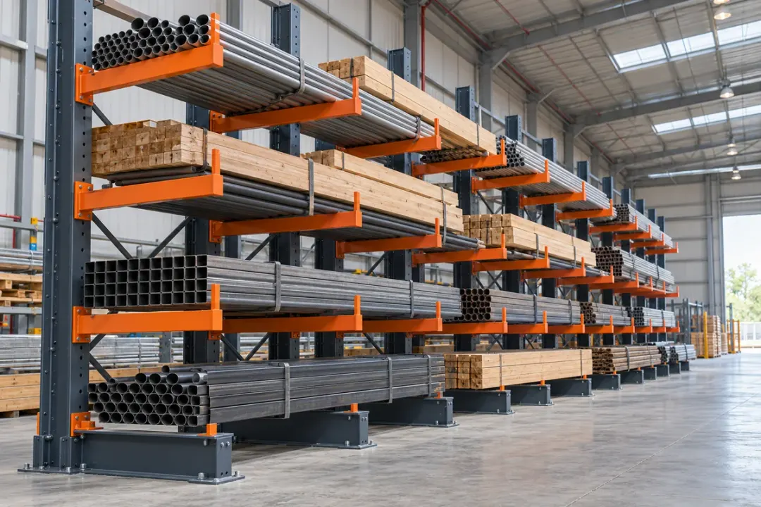
Cantilever storage racks with long goods, upright columns, projecting arms and floor-mounted bases.
Cantilever racking

Keep an angle history for cantilever-rack columns carrying tubes, timber or other long goods. Relate the H310-TS380C reference to the column, arm arrangement and representative load distribution. The resulting local inclination record provides context for inspection after handling contact or rack adjustment, where the project requires the ±0.01° accuracy grade.

Inclination to monitor
Local inclination of the selected cantilever-rack upright relative to its commissioning reference.
Monitoring point
A rigid position on the selected cantilever-rack upright, clear of storage arms and handling contact.
Plan your installation
Share upright and base details, arm loading patterns, stored product lengths, handling clearances and the rack inspection plan.
Discuss this application

Drive-in pallet racking

Local inclination of the selected drive-in rack upright under documented loading conditions.
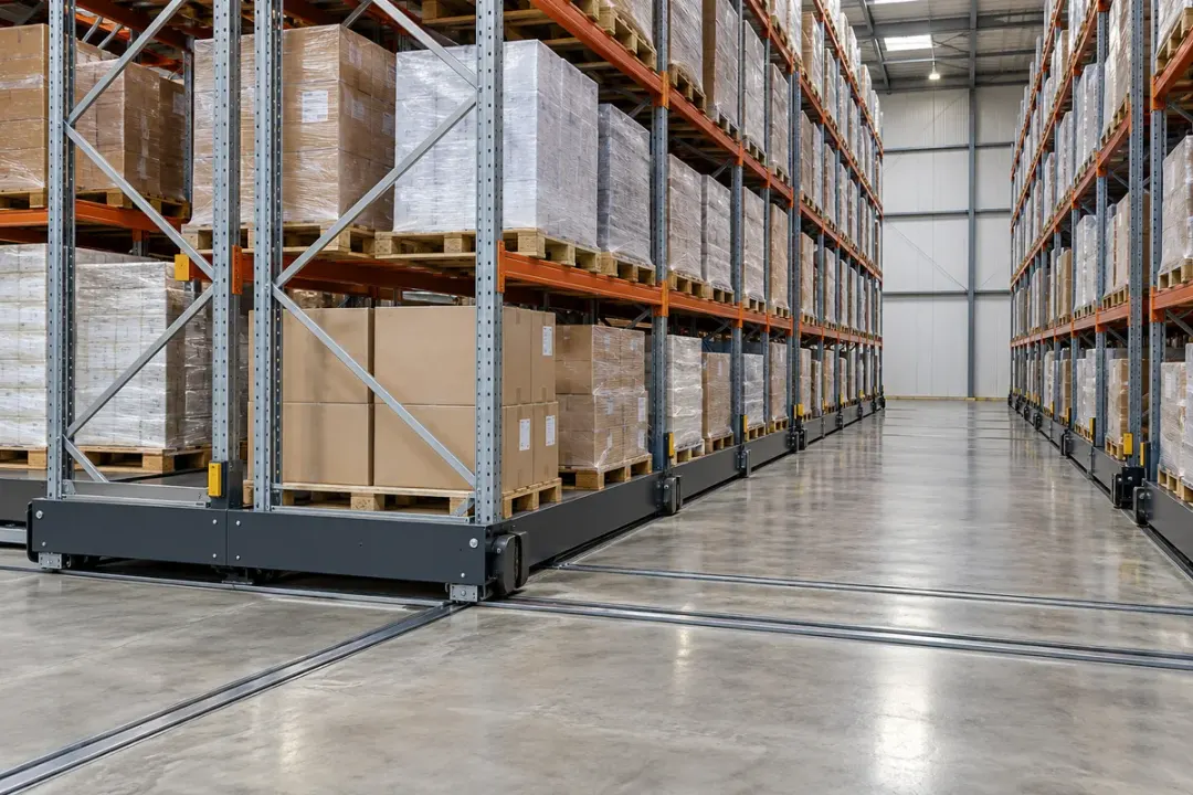
Drive-in pallet racking with deep storage lanes, upright frames and horizontal pallet-support rails.
Drive-in pallet racking

Follow selected upright sections within drive-in or drive-through pallet lanes. Document the H310-TS380C mounting direction and compare readings against the installation reference at equivalent lane-loading states. This gives inspection teams a local angle record around reported vehicle contact, support-rail work or structural maintenance, with each point linked to a specific storage lane.
Inclination to monitor
Local inclination of the selected drive-in rack upright under documented loading conditions.
Monitoring point
An approved rack upright position outside forklift travel paths and pallet-support clearances.
Plan your installation
Provide lane depth, rack layout, support-rail arrangement, loading sequence, handling clearances and inspection responsibilities.
Discuss this application

Mobile pallet racking

Static inclination of the selected upright at the agreed parked position and loading state.
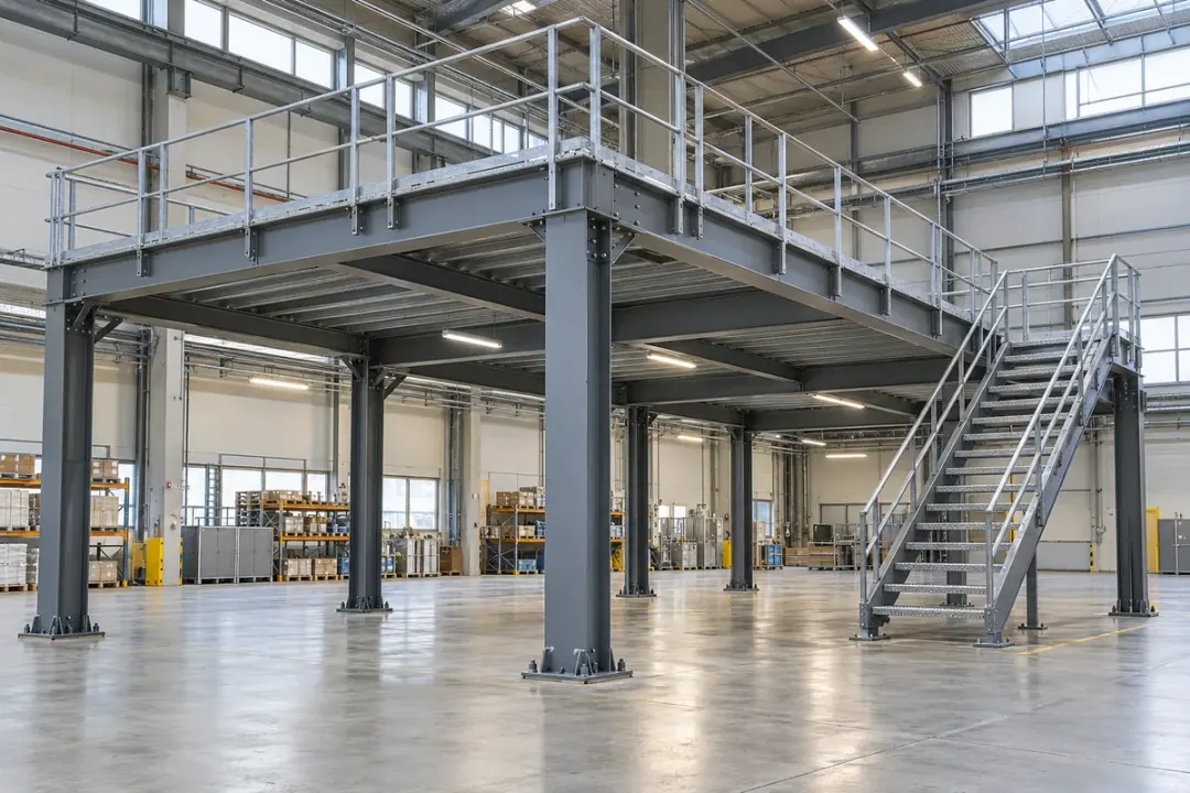
Mobile pallet racks on steel bases and floor rails beside an open warehouse aisle.
Mobile pallet racking

Compare the inclination of a selected mobile-rack upright at defined stationary positions. Use the H310-TS380C reference after the carriage has settled, recording its location and load condition. This supports finer local-angle comparisons around rack maintenance and re-levelling; the one-minute acquisition profile is not a substitute for motion control or collision detection.
Inclination to monitor
Static inclination of the selected upright at the agreed parked position and loading state.
Monitoring point
A rigid upright point clear of moving equipment, compared at agreed stationary carriage positions.
Plan your installation
Confirm mobile-base design, parked reference position, rack loads, travel clearances, movement schedule and maintenance access.
Discuss this application

Mezzanine columns

Local inclination of the selected mezzanine support column along the defined measurement direction.
Steel mezzanine platform with visible support columns inside a factory.
Mezzanine columns

Associate local inclination readings with the column grid of a warehouse mezzanine. The H310-TS380C can provide a finer angular record at approved structural points during documented loading and maintenance stages. Keep the sensor’s axis reference with the column identifier so comparisons remain tied to the same support rather than removable cladding.

Inclination to monitor
Local inclination of the selected mezzanine support column along the defined measurement direction.
Monitoring point
A structural column location selected in the platform monitoring plan.
Plan your installation
Column grid, platform loads, connection details, altered layouts, inspection access.
Discuss this application
02Poles & towers6 monitoring tasks
Application illustration: Street-light poles and their bases beside a landscaped urban road.
Poles & towers

Lighting, power, telecom and roadside supports, identified by asset number and an approved structural fixing.

Street light poles

Local inclination of the monitored pole section relative to the recorded installation reference.
Application illustration: Street-light poles and their bases beside a landscaped urban road.
Street light poles

Track local inclination at an approved section of a street-light pole. The H310-TS380C supports projects specifying ±0.01° accuracy for repeatable angle comparisons before and after base work, pole servicing or reported vehicle contact. Preserve the pole identifier and axis orientation, and review the trend alongside site observations and maintenance records.
Inclination to monitor
Local inclination of the monitored pole section relative to the recorded installation reference.
Monitoring point
The pole or structural support selected for monitoring.
Plan your installation
Provide pole dimensions, mounting height, local network coverage and the required reporting schedule.
Discuss this application

Transmission towers

Local angular change of the selected transmission-tower member at its fixed mounting point.
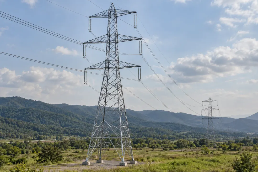
Application illustration: Steel electricity transmission pylons with crossarms, insulators and overhead conductors.
Transmission towers

Follow local inclination at selected transmission-tower members using a documented X/Y/Z sensing-axis convention. The H310-TS380C is suited to a specified ±0.01° accuracy objective at the mounting point. Link its records to tower inspections, member work and foundation observations; a single local sensor does not describe the whole tower’s deformation.
Inclination to monitor
Local angular change of the selected transmission-tower member at its fixed mounting point.
Monitoring point
Structural members identified for the tower’s monitoring objective.
Plan your installation
Identify the tower member, mounting arrangement, site access requirements and any complementary foundation measurements.
Discuss this application

Telecom towers

Local inclination of the selected mast section, tower member or structural support.
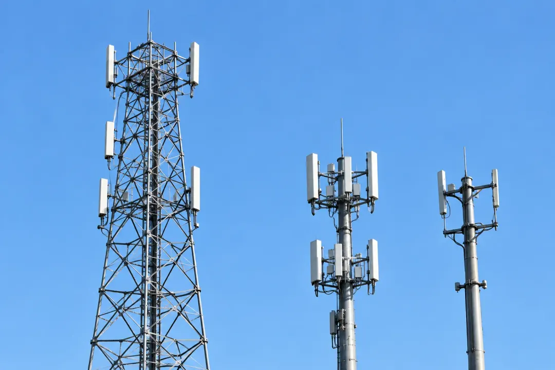
Application illustration: A telecommunications lattice tower with cellular antenna panels against the sky.
Telecom towers

Record local inclination at a defined telecom-tower member before and after equipment or maintenance work. The H310-TS380C’s ±0.01° accuracy grade is relevant where the project requires a finer angle record at that point. Keep antenna changes, wind context and fixing orientation with the record; heading and antenna azimuth require separate measurement methods.

Inclination to monitor
Local inclination of the selected mast section, tower member or structural support.
Monitoring point
Selected mast sections, tower members or structural supports.
Plan your installation
Share the tower layout, monitored elements, wireless coverage and the platform used by your maintenance team.
Discuss this application

Billboard support poles

Local inclination of the selected billboard pole or frame member from its reference orientation.
Application illustration: A blank roadside billboard on a steel monopole with visible supporting bracing.
Billboard support poles

Compare the inclination of a billboard’s support pole at the same approved fixing point. The H310-TS380C provides the ±0.01° accuracy grade for finer local-angle review around support maintenance, panel replacement and base works. Record wind conditions and work stages so the sign owner can relate a persistent change to the correct structural member.

Inclination to monitor
Local inclination of the selected billboard pole or frame member from its reference orientation.
Monitoring point
The support pole or frame member selected in the project plan.
Plan your installation
Provide support dimensions, mounting access, site exposure and the required measurement and notification schedule.
Discuss this application

Roadside equipment poles

Local inclination of a selected roadside pole or fixed crossarm support relative to its installation reference.
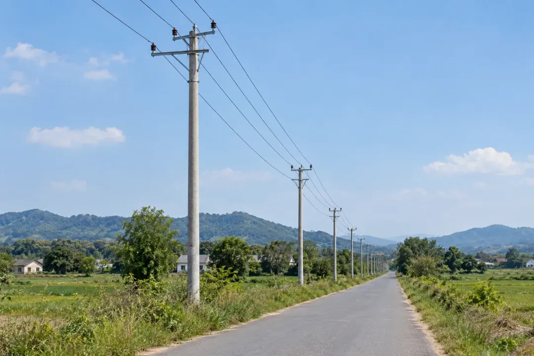
Roadside equipment poles along a landscaped urban road.
Roadside equipment poles

Follow local inclination at selected roadside equipment poles and crossarm supports. A fixed mounting reference lets H310-TS380C records be compared through roadworks, equipment servicing and reported contact. Use the ±0.01° accuracy grade where specified, while treating camera alignment, equipment pointing and traffic-system operation as separate functions.
Inclination to monitor
Local inclination of a selected roadside pole or fixed crossarm support relative to its installation reference.
Monitoring point
An approved rigid pole or crossarm-support section, clear of adjustable equipment brackets.
Plan your installation
Pole identifier, member and mounting height, equipment layout, access permissions and required local-angle accuracy.
Discuss this application

Distribution poles

Local inclination of the selected distribution pole relative to its documented installation reference.
Distribution poles with crossarms along a rural roadside.
Distribution poles

Observe local inclination on approved distribution poles with a named installation reference. The H310-TS380C supports finer angle comparisons where the utility specifies ±0.01° accuracy. Record the measurement direction, feeder section and nearby ground works so later observations can be reviewed with pole-condition and foundation inspections.

Inclination to monitor
Local inclination of the selected distribution pole relative to its documented installation reference.
Monitoring point
The designated rigid section of the distribution pole.
Plan your installation
Pole material and number; pole-mounted equipment layout; roadside drainage conditions; utility access permissions; feeder maintenance schedule.
Discuss this application
03Bridges, roads & ports6 monitoring tasks
Application illustration: A concrete bridge crossing water with piers and green hills in the background.
Bridges, roads & ports

Local inclination at selected bridge, retaining-wall and marine structural points, interpreted with the project’s engineering records.

Bridge elements

Local angular change at the selected bridge pier, abutment or structural-member mounting point.
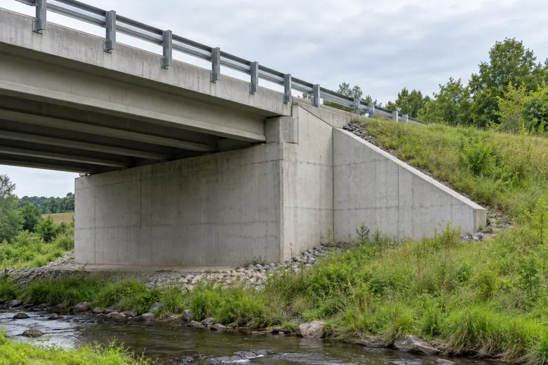
Application illustration: A concrete bridge crossing water with piers and green hills in the background.
Bridge elements

Follow local inclination at engineer-selected bridge piers or rigid structural members. The H310-TS380C provides the ±0.01° accuracy grade for an agreed local rotation objective and reference condition. Compare readings alongside loading, temperature and inspection records; displacement, deck deflection and structural condition require their own engineering measurements and assessment.
Inclination to monitor
Local angular change at the selected bridge pier, abutment or structural-member mounting point.
Monitoring point
Piers, abutments or members identified in the bridge monitoring plan.
Plan your installation
State the monitoring objective, mounting positions and working angle range; include survey requirements where displacement is also needed.
Discuss this application

Bridge abutments & wing walls

Local inclination of the selected abutment or wing-wall surface along the agreed measurement direction.
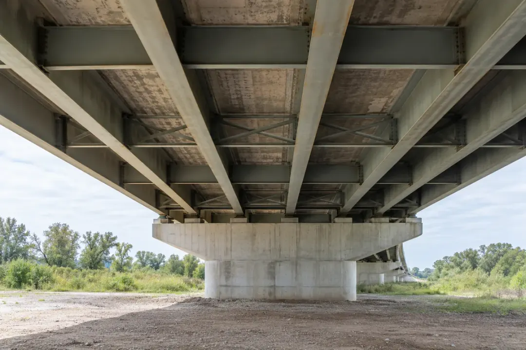
Concrete bridge abutment and wing wall beside an approach embankment.
Bridge abutments & wing walls

Record inclination at selected abutment or wing-wall points with a stable mounting reference. The H310-TS380C suits a project that specifies ±0.01° accuracy for local-angle comparisons around adjacent earthworks, drainage changes or bridge maintenance. Relate each point to the engineer’s drawing and complementary survey observations.
Inclination to monitor
Local inclination of the selected abutment or wing-wall surface along the agreed measurement direction.
Monitoring point
A designated face of the abutment or a selected wing-wall section.
Plan your installation
Abutment or wall drawing; backfill and drainage layout; nearby works schedule; mounting access.
Discuss this application

Bridge-deck structural points

Local angular change at the designated bridge-deck point under comparable observation conditions.
Underside of a bridge deck showing main girders and cross-members.
Bridge-deck structural points

Compare local orientation at a selected rigid bridge-deck member under defined reference conditions. The H310-TS380C’s ±0.01° accuracy grade can support an engineer-specified rotation task, with traffic and temperature context recorded. Measurements describe the installed point’s inclination; they do not directly provide deck deflection, displacement or a complete dynamic response.
Inclination to monitor
Local angular change at the designated bridge-deck point under comparable observation conditions.
Monitoring point
A designated rigid location on the monitored deck member.
Plan your installation
Deck-member drawing; rotation axis; comparable vehicle-loading conditions; observation schedule.
Discuss this application

Highway retaining walls

Local inclination of the selected retaining-wall body relative to the installation baseline.
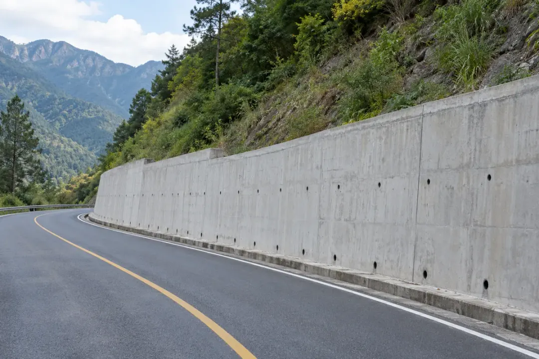
Highway retaining wall with drainage outlets beside a mountain road.
Highway retaining walls

Follow local inclination at selected retaining-wall sections beside roads or embankments. The H310-TS380C supports finer angular comparisons where ±0.01° accuracy is specified, with each sensor tied to a wall chainage and fixing direction. Review the readings with drainage conditions, nearby works and the engineer’s wider ground-monitoring plan.
Inclination to monitor
Local inclination of the selected retaining-wall body relative to the installation baseline.
Monitoring point
A rigid surface on the selected retaining-wall section.
Plan your installation
Wall type and section layout; drainage locations; roadside access restrictions; monitoring directions.
Discuss this application

Quay walls

Local angular change of the selected quay-wall section at its documented mounting point.
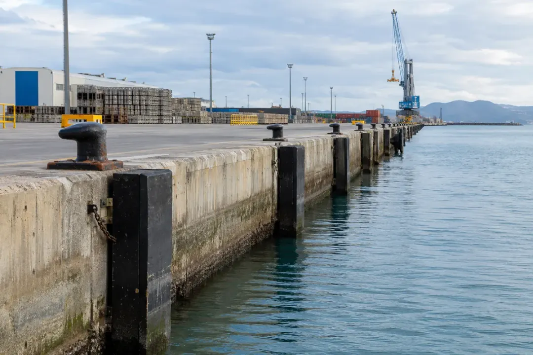
Concrete quay wall and working apron along an operating port.
Quay walls

Keep a local inclination reference on approved quay-wall structural points. The H310-TS380C supports a specified ±0.01° accuracy task through documented loading, tide and maintenance conditions. Assign every reading to the wall section and mounting direction so the record can be reviewed with marine surveys and the port’s inspection information.
Inclination to monitor
Local angular change of the selected quay-wall section at its documented mounting point.
Monitoring point
A selected rigid quay-wall element accessible from the working side.
Plan your installation
Quay-wall type; tidal exposure; operating-load conditions; corrosion and mounting requirements.
Discuss this application

Jetty supports

Local inclination of the selected fixed jetty support member relative to its reference orientation.
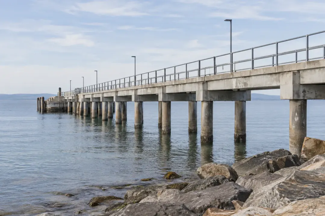
Fixed piles and beams supporting a coastal jetty.
Jetty supports

Monitor local inclination at selected jetty pile heads or rigid support members. The H310-TS380C’s ±0.01° accuracy grade is relevant where the design calls for finer angle comparisons at those points. Record tide, loading and the reference state, and select enclosure and mounting details for the actual marine exposure.
Inclination to monitor
Local inclination of the selected fixed jetty support member relative to its reference orientation.
Monitoring point
A designated fixed pile, column or support member.
Plan your installation
Support-member geometry; tidal access window; vessel-operation periods; marine exposure conditions.
Discuss this application
04Railways & tunnels6 monitoring tasks
Application illustration: An electrified railway corridor with rails, catenary supports and a retaining wall.
Railways & tunnels

Operator-approved fixed structures along rail, metro and tunnel routes, with chainage and installation references retained.

Railway infrastructure

Local inclination of the approved retaining wall, catenary support or stationary railway member.
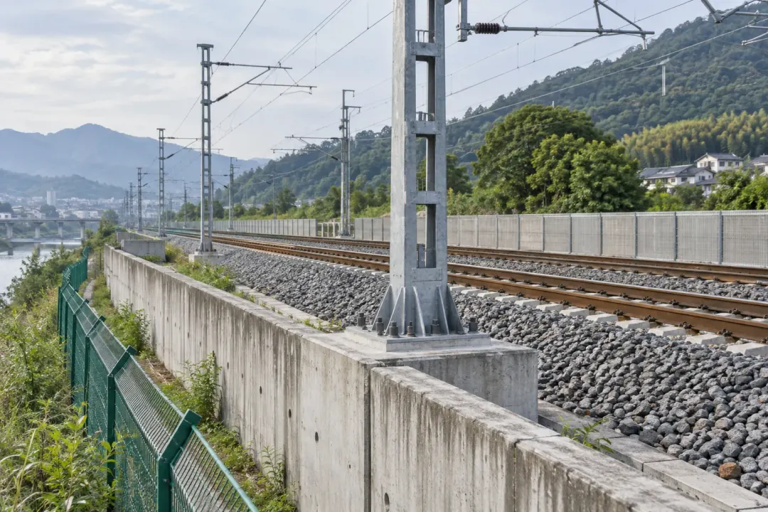
Application illustration: An electrified railway corridor with rails, catenary supports and a retaining wall.
Railway infrastructure

Follow local inclination at railway-side retaining walls, support members or other engineer-defined fixed structures. The H310-TS380C provides the ±0.01° accuracy grade for the selected local-angle objective. Maintain the route reference, mounting orientation and work-stage record; rail geometry, track alignment and train-induced vibration remain separate measurement tasks.
Inclination to monitor
Local inclination of the approved retaining wall, catenary support or stationary railway member.
Monitoring point
Approved points on retaining walls, catenary supports or stationary members.
Plan your installation
Share the site access plan, operating conditions, communications route and required notification time.
Discuss this application

Tunnel monitoring

Local angular change of the selected tunnel lining segment or structural support.
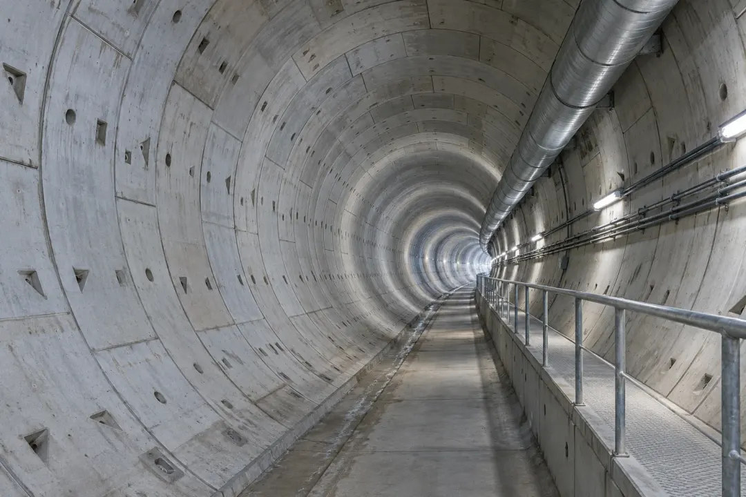
Application illustration: Segmental concrete tunnel lining with visible joints and a service walkway.
Tunnel monitoring

Record inclination at approved tunnel-lining segments or rigid internal support points. The H310-TS380C can support a ±0.01° accuracy objective within a defined monitoring plan. Keep chainage, segment identity and axis convention with the reference, using survey methods or additional instruments when convergence, displacement or a wider tunnel response is required.
Inclination to monitor
Local angular change of the selected tunnel lining segment or structural support.
Monitoring point
Selected lining segments, structural supports or approved mounting points.
Plan your installation
Provide the tunnel section, monitoring locations, underground communications route and any separate convergence measurement requirements.
Discuss this application

Metro and subway structures

Local inclination of the monitored station column, tunnel element or retaining structure.
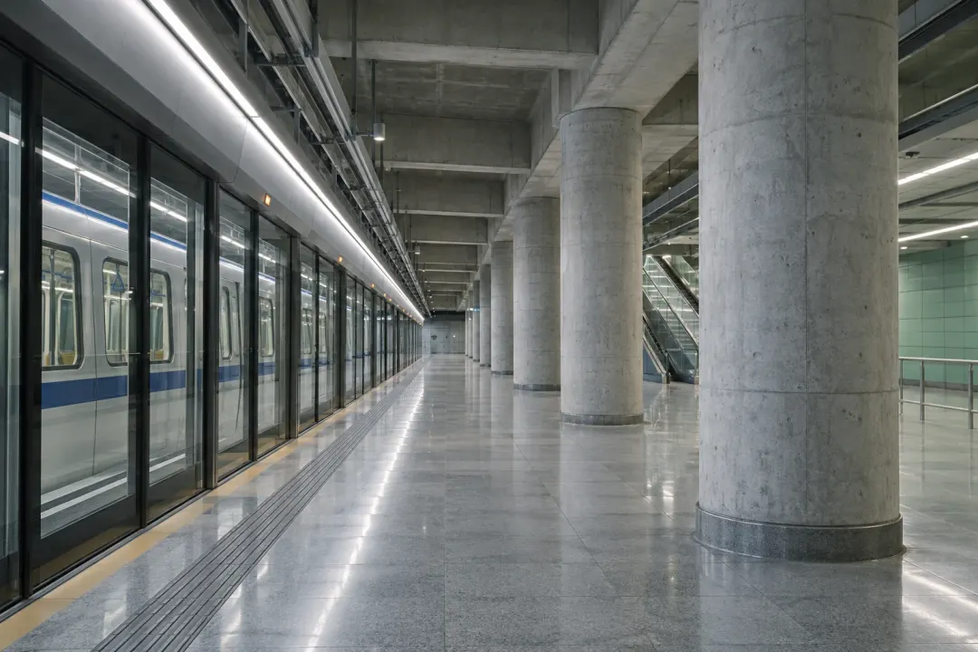
Application illustration: Underground metro station columns, ceiling beams and platform screen doors.
Metro and subway structures

Compare local inclination at selected metro-station columns, tunnel members or other fixed structural points. The H310-TS380C supports an agreed ±0.01° accuracy task with a documented reference and axis orientation. Associate records with work periods and inspection findings, while the operator’s separate systems handle train operation and dynamic rail measurements.
Inclination to monitor
Local inclination of the monitored station column, tunnel element or retaining structure.
Monitoring point
Station columns, tunnel elements or retaining structures in the monitoring design.
Plan your installation
Share the work stages, permitted access times, mounting constraints and route from underground sensors to the platform.
Discuss this application

Catenary masts

Local inclination of the selected catenary mast at its defined structural mounting point.
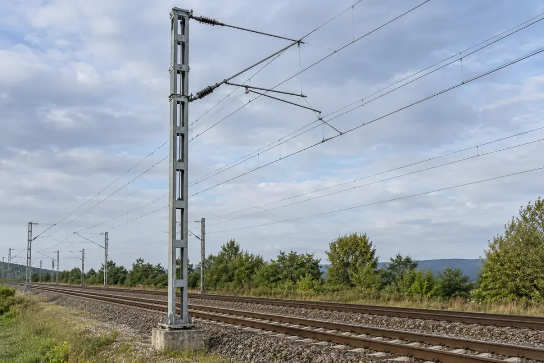
Railway catenary support mast, base and overhead contact wires.
Catenary masts

Follow local inclination at an approved rigid section of a railway catenary mast. The H310-TS380C is relevant where ±0.01° accuracy is specified for the mast reference. Keep the mounting elevation and direction with maintenance records; contact-wire geometry, tension and electrical clearances require the railway operator’s dedicated methods.
Inclination to monitor
Local inclination of the selected catenary mast at its defined structural mounting point.
Monitoring point
Secure to the mast at the operator-approved position and orientation.
Plan your installation
Mast type; asset reference; approved mounting zone; electrical clearances; maintenance access.
Discuss this application

Track-support slabs

Slow local rotation of the selected track-support slab under comparable observation conditions.
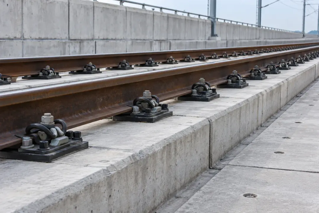
Ballastless track with concrete support slabs and rail fastenings.
Track-support slabs

Record local inclination on an engineer-selected track-support slab or fixed base. The H310-TS380C’s ±0.01° accuracy grade can support a defined rotation comparison during agreed reference states. Associate the sensor with the slab and route chainage, while keeping track gauge, alignment, displacement and dynamic loading measurements within their dedicated survey systems.
Inclination to monitor
Slow local rotation of the selected track-support slab under comparable observation conditions.
Monitoring point
Use an engineered fixing on the approved slab or base-element location.
Plan your installation
Slab type; measurement axes; reference conditions; fastening design; operator approval.
Discuss this application

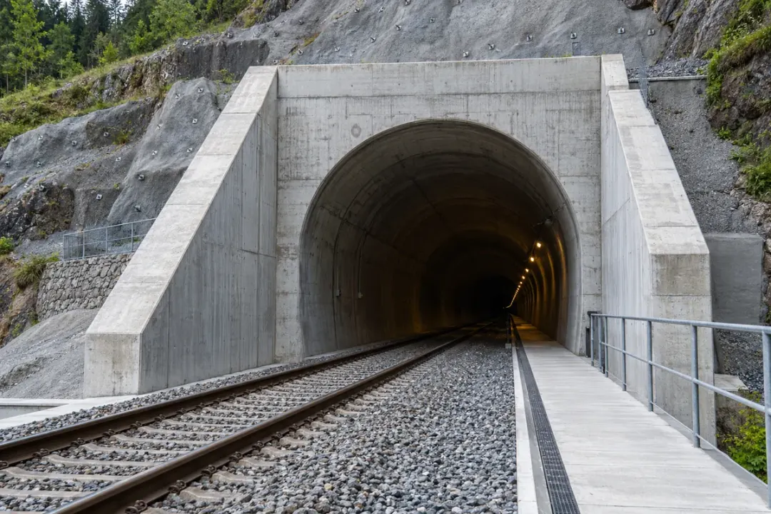
Tunnel portals

Local inclination of the selected tunnel-portal wall or engineered support element.
Tunnel portal with concrete headwall and engineered support structures.
Tunnel portals

Follow local inclination at selected tunnel-portal or approach-support members. A documented H310-TS380C reference supports finer angular comparisons where ±0.01° accuracy is required through construction, maintenance or nearby slope works. Identify the structural point and work stage, and review the readings with drainage, geological and survey observations.
Inclination to monitor
Local inclination of the selected tunnel-portal wall or engineered support element.
Monitoring point
Fix to the designated portal wall or structural support member.
Plan your installation
Portal arrangement; support stage; monitored member; work sequence; installation access.
Discuss this application
05Slopes, dams & embankments6 monitoring tasks
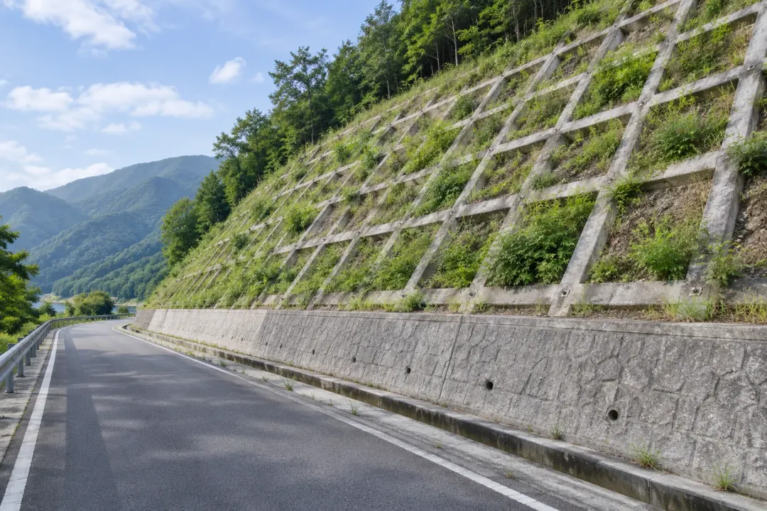
Application illustration: An engineered cut slope with stabilization lattice, vegetation and a drainage channel.
Slopes, dams & embankments

Rigid facing and support elements selected within an engineering plan for slopes, dikes, dams and retaining structures.

Slopes and embankments

Local inclination of the selected surface monitoring element or retaining structure.
Application illustration: An engineered cut slope with stabilization lattice, vegetation and a drainage channel.
Slopes and embankments

Observe inclination at engineered slope-facing or retaining elements selected by the geotechnical team. The H310-TS380C supports a specified ±0.01° accuracy task at the rigid mounting point. Record rainfall, drainage and work-stage context; the surface angle record forms one part of the project’s plan for surveying and subsurface or ground-movement measurements.
Inclination to monitor
Local inclination of the selected surface monitoring element or retaining structure.
Monitoring point
Surface elements or retaining structures selected by the monitoring designer.
Plan your installation
Provide the slope layout, surface fixing method, site exposure and the wider monitoring plan for ground movement.
Discuss this application

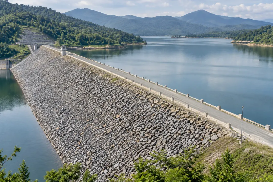
Sea dikes, dams and reservoir slopes

Local inclination of the designated surface structure, facing element or retaining member.
Application illustration: An embankment dam with a riprap slope, crest road and adjacent reservoir.
Sea dikes, dams and reservoir slopes

Follow local inclination at approved sea-dike facing or reservoir-side structural elements. The H310-TS380C can support finer reference comparisons where ±0.01° accuracy is specified. Relate each point to water levels, loading and inspection stages; hydrological conditions and ground displacement remain part of the wider engineering monitoring plan.
Inclination to monitor
Local inclination of the designated surface structure, facing element or retaining member.
Monitoring point
Defined surface structures, facing elements or retaining members.
Plan your installation
State mounting locations, splash or immersion exposure, inspection access and the measurement and reporting profile.
Discuss this application

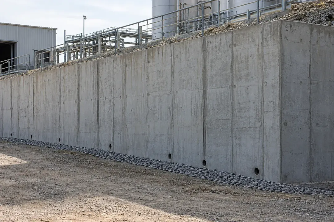
Retaining walls

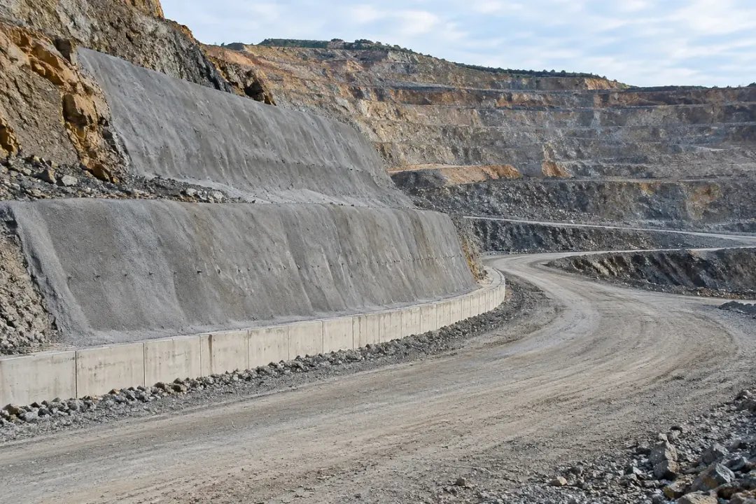
Local inclination of the selected embankment or industrial-platform retaining-wall section.
Concrete retaining wall supporting an embankment or industrial platform.
Retaining walls

Record local inclination at a designated retaining-wall panel or structural element. The H310-TS380C’s ±0.01° accuracy grade suits projects requiring a finer angle reference around changes in retained loading or adjacent work. Keep the sensor point linked to the engineer’s wall section and complementary survey or ground-monitoring data.
Inclination to monitor
Local inclination of the selected embankment or industrial-platform retaining-wall section.
Monitoring point
Fix to the selected retaining-wall body at the specified orientation.
Plan your installation
Wall type; retained height; nearby loading; construction sequence; mounting surface.
Discuss this application

Open-pit retaining structures

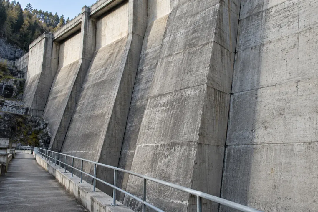
Local angular change of the selected engineered facing or retaining element on the bench.
Open-pit benches with an engineered facing section and access road.
Open-pit retaining structures

Follow inclination at engineered retaining or support elements on an open-pit bench. The H310-TS380C can provide a ±0.01° accuracy reference at points selected by the geotechnical team. Relate readings to excavation stages and site inspections, using a suitable mounting and enclosure; the sensor’s local angle history does not establish overall slope stability.
Inclination to monitor
Local angular change of the selected engineered facing or retaining element on the bench.
Monitoring point
Mount on a designed facing or retaining element selected for monitoring.
Plan your installation
Bench arrangement; monitored element; excavation schedule; blasting schedule; access conditions.
Discuss this application

Concrete dams

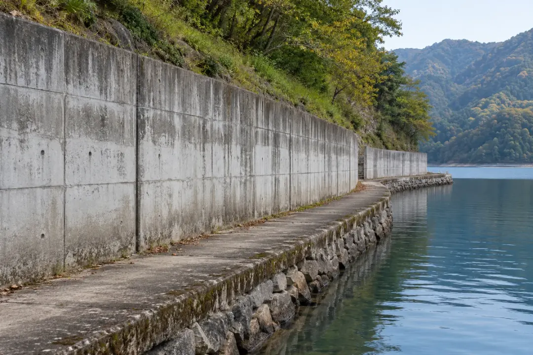
Local angular change at the designated dam-block surface along the documented measurement axes.
Concrete dam blocks with visible joints and an inspection walkway.
Concrete dams

Compare local inclination at approved structural points on a concrete dam. The H310-TS380C supports an engineering brief specifying ±0.01° accuracy, with water level, temperature and reference conditions recorded. Keep point identifiers and supplied angle definitions consistent so the readings can be reviewed alongside the dam’s established survey and instrumentation programme.
Inclination to monitor
Local angular change at the designated dam-block surface along the documented measurement axes.
Monitoring point
Fix directly to the designated dam-block surface at the surveyed orientation.
Plan your installation
Dam-block reference; measurement axes; mounting elevation; inspection access; existing monitoring plan.
Discuss this application

Reservoir-bank retaining walls

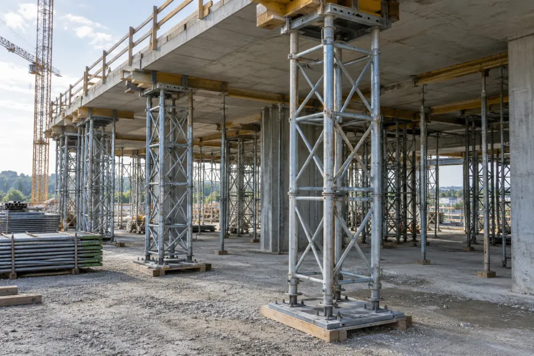
Local inclination of the selected shoreline retaining wall or engineered support element.
Reservoir shoreline retaining wall beside a maintenance path.
Reservoir-bank retaining walls

Follow local inclination at selected reservoir-bank retaining-wall sections. Use the H310-TS380C for projects specifying ±0.01° accuracy at the approved mounting points. Document water-level conditions, drainage work and wall identifiers before comparing the reference, and combine the record with the engineer’s survey and ground observations.
Inclination to monitor
Local inclination of the selected shoreline retaining wall or engineered support element.
Monitoring point
Secure to the selected shoreline retaining wall or structural support element.
Plan your installation
Bank section; retaining form; water-level exposure zone; shoreline access; maintenance programme.
Discuss this application
06Construction & temporary works6 monitoring tasks
Application illustration: Temporary steel shoring and braced support towers beneath a concrete deck under construction.
Construction & temporary works

Named structural points across erection, loading and maintenance stages, with reference conditions documented.

Construction and temporary structures

Local rotation of the approved temporary support, retaining structure or neighbouring structural element.
Application illustration: Temporary steel shoring and braced support towers beneath a concrete deck under construction.
Construction and temporary structures

Record local inclination at engineer-selected temporary supports through defined construction stages. The H310-TS380C’s ±0.01° accuracy grade is useful where the monitoring design requires a finer angular reference. Preserve the support identifier, axis convention and load stage, and review readings with inspections and the approved temporary-works plan.
Inclination to monitor
Local rotation of the approved temporary support, retaining structure or neighbouring structural element.
Monitoring point
Approved points on temporary supports, retaining structures or neighbouring assets.
Plan your installation
Share the construction sequence, planned sensor moves and the project’s notification and inspection process.
Discuss this application

Excavation retaining walls

Local inclination of the selected excavation retaining-wall section at the specified structural point.
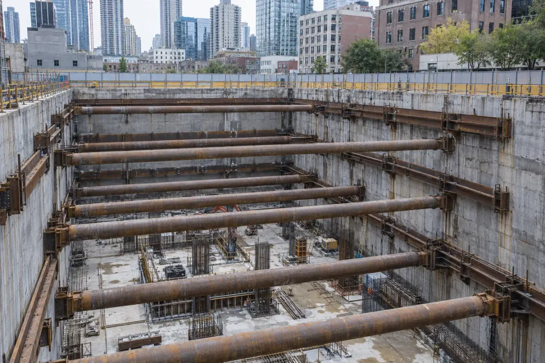
Excavation retaining walls with installed horizontal supports.
Excavation retaining walls

Follow local inclination at selected excavation-retaining-wall points during defined work stages. The H310-TS380C supports a ±0.01° accuracy objective where specified by the monitoring designer. Record excavation level, bracing changes and mounting direction; the surface angle record should be considered with the project’s survey, settlement and ground-instrumentation results.
Inclination to monitor
Local inclination of the selected excavation retaining-wall section at the specified structural point.
Monitoring point
A designated rigid face of the retaining-wall element.
Plan your installation
Retaining-wall system; excavation stages; support sequence; required measurement axes.
Discuss this application

Falsework & formwork supports

Local inclination of the approved temporary support-frame member under the agreed project conditions.
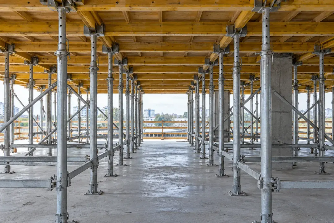
Formwork support frame with uprights, bracing and top supports.
Falsework & formwork supports

Compare local inclination at approved falsework or formwork support members. A fixed H310-TS380C reference supports finer angle review, with the ±0.01° accuracy grade selected in the temporary-works design. Relate each point to assembly, loading and striking stages, keeping the angle record alongside support inspections and the responsible engineer’s procedures.
Inclination to monitor
Local inclination of the approved temporary support-frame member under the agreed project conditions.
Monitoring point
An engineer-selected upright or rigid support-frame member.
Plan your installation
Engineered support layout; member designation; pour or loading sequence; installation clearance.
Discuss this application

Steel-column erection

Local inclination of the selected steel column along the defined erection-monitoring direction.
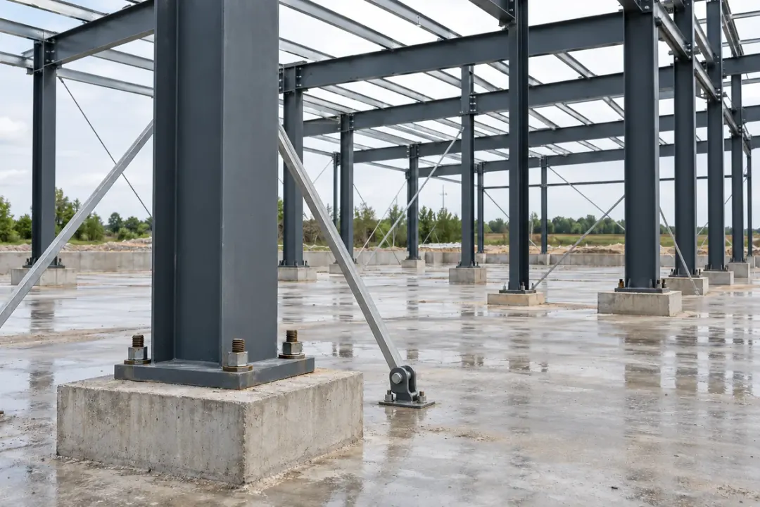
Erected steel columns with base plates and temporary bracing.
Steel-column erection

Follow local inclination at a selected steel column or frame member during erection stages. The H310-TS380C provides the ±0.01° accuracy grade for an agreed local-angle comparison after the member is stable. Record the mounting direction, bracing and connection stage, using the project’s survey instruments to establish geometry and final alignment.
Inclination to monitor
Local inclination of the selected steel column along the defined erection-monitoring direction.
Monitoring point
A designated rigid mounting face on the selected steel column.
Plan your installation
Column section; erection sequence; bracing and connection stages; survey reference plan.
Discuss this application

Buildings beside construction

Local angular change of the approved load-bearing building member beside the works.
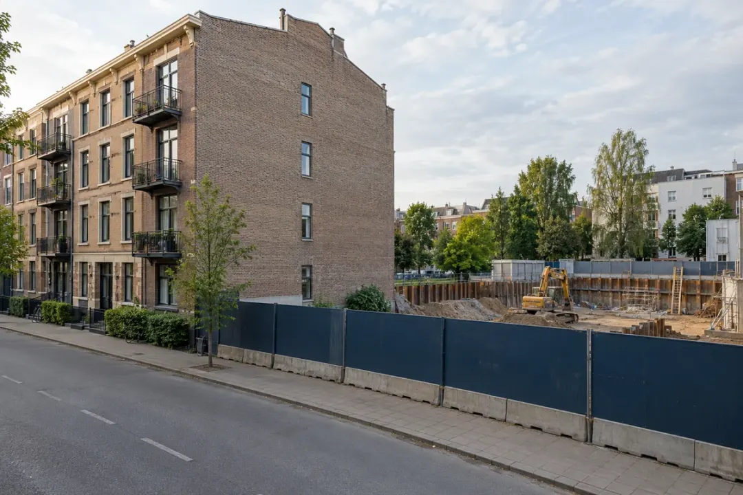
Existing building beside a construction-site boundary.
Buildings beside construction

Record local inclination at engineer-selected points on a building beside construction work. The H310-TS380C can support a specified ±0.01° accuracy objective with owner-approved mounting and a documented reference. Relate changes to work stages, temperature and inspections, and combine the record with the project’s settlement, crack and survey measurements.
Inclination to monitor
Local angular change of the approved load-bearing building member beside the works.
Monitoring point
A selected structural wall, column or other designated rigid element.
Plan your installation
Building structure and condition; distance to works; mounting permission; pre-work baseline period.
Discuss this application

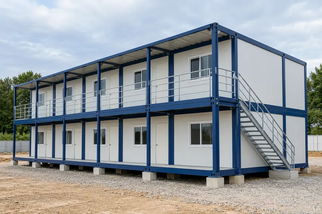
Modular & site buildings

Local inclination of the selected modular-building base frame or fixed structural support.
Modular site buildings with visible frame and ground supports.
Modular & site buildings

Compare local orientation at selected structural frames of modular or site buildings after installation. The H310-TS380C supports a ±0.01° accuracy reference where the project needs finer angular review through support adjustment or relocation. Record the module ID and stable reference state, while separate surveys establish foundation levels and overall geometry.

Inclination to monitor
Local inclination of the selected modular-building base frame or fixed structural support.
Monitoring point
A rigid frame column or beam designated in the monitoring layout.
Plan your installation
Module layout; support and anchorage details; relocation plan; intended occupancy period.
Discuss this application
07Heritage, buildings & trees6 monitoring tasks
Application illustration: A traditional pagoda surrounded by mature trees and landscaped grounds.
Heritage, buildings & trees

Conservation- or arborist-approved measuring points on buildings, historic members and trees.

Heritage buildings and ancient pagodas

Local inclination of the agreed heritage structural element at the approved mounting position.
Application illustration: A traditional pagoda surrounded by mature trees and landscaped grounds.
Heritage buildings and ancient pagodas

Follow local inclination at conservation-approved structural points in heritage buildings or pagodas. The H310-TS380C’s ±0.01° accuracy grade supports a finer angle reference where required by the conservation plan. Use an agreed, compatible fixing and retain the member identity, axis convention and intervention history with the readings.
Inclination to monitor
Local inclination of the agreed heritage structural element at the approved mounting position.
Monitoring point
Structural elements and fixing locations agreed with the conservation team.
Plan your installation
Include the approved attachment method, surface restrictions, access arrangements and intended monitoring period.
Discuss this application

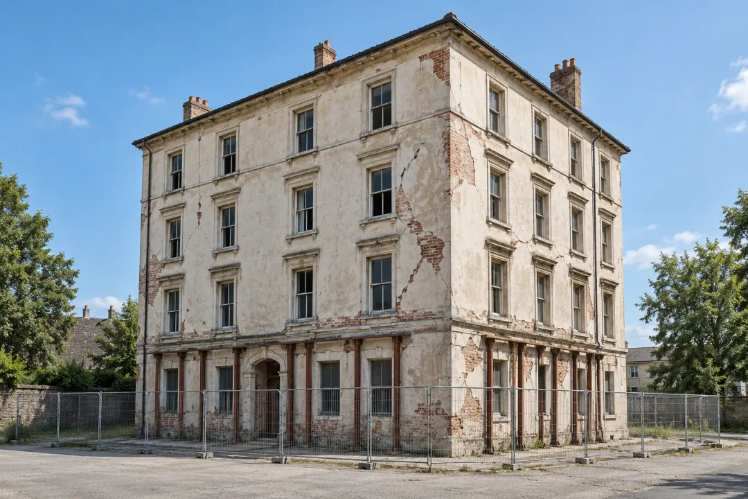
Existing buildings & repair works

Local angular change of the engineer-selected load-bearing wall, column or structural member.
Application illustration: Ageing masonry building with visible facade cracks, temporary supports and a perimeter barrier, representing a building under structural assessment.
Existing buildings & repair works

Record local inclination at engineer-approved points in an existing building undergoing investigation or repair. The H310-TS380C provides the ±0.01° accuracy grade for a defined angle task, with a stable reference and intervention log. Interpret readings with surveys and inspections; they are not a diagnosis of structural condition or permission for occupancy.

Inclination to monitor
Local angular change of the engineer-selected load-bearing wall, column or structural member.
Monitoring point
Load-bearing walls, columns or other structural members selected by the engineer.
Plan your installation
Provide the site access plan, approved monitoring points, required notification time and engineering review process.
Discuss this application

Urban trees

Local inclination of the trunk at the documented attachment position and measurement direction.
Application illustration: A mature urban tree with a visible trunk and root flare beside a paved park path.
Urban trees

Follow the local inclination of a selected tree-trunk section using an arborist-approved mounting. The H310-TS380C can support a ±0.01° accuracy reference where useful, with the trunk point and sensor orientation documented. Review the record with weather, ground and inspection observations; local tilt alone does not determine root condition or failure risk.
Inclination to monitor
Local inclination of the trunk at the documented attachment position and measurement direction.
Monitoring point
An arborist-selected trunk section with an approved non-injurious attachment checked throughout the monitoring period.
Plan your installation
Identify the tree, attachment method, growth-related inspection needs and environmental conditions used for comparison.
Discuss this application

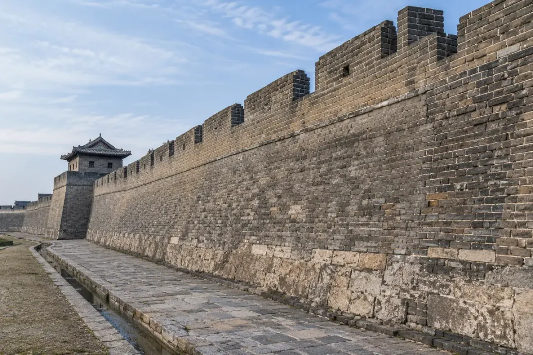
Historic masonry walls

Local inclination of the selected masonry wall surface at the conservation-approved mounting point.
Historic masonry wall with visible brickwork and a continuous wall profile.
Historic masonry walls

Compare local inclination at conservation-approved points on historic masonry walls. The H310-TS380C supports projects specifying ±0.01° accuracy, with the wall section and compatible fixing documented. Connect readings to weather, drainage and intervention records, and review the local angle alongside masonry inspections and any separate survey or crack measurements.

Inclination to monitor
Local inclination of the selected masonry wall surface at the conservation-approved mounting point.
Monitoring point
A defined wall section at a conservation-approved attachment location.
Plan your installation
Wall construction and surface condition; crack survey; drainage context; permitted attachment; conservation access restrictions.
Discuss this application

Historic timber frames

Local angular change of the selected timber post or structural member at the approved fixing.
Historic timber column and beam joints inside a traditional building.
Historic timber frames

Follow local inclination at selected historic timber-frame members with a conservation-approved fixing. The H310-TS380C’s ±0.01° accuracy grade can support finer angle comparisons through recorded maintenance and environmental conditions. Preserve the member ID and mounting reference, and combine the readings with inspections of connections, supports and the surrounding building fabric.

Inclination to monitor
Local angular change of the selected timber post or structural member at the approved fixing.
Monitoring point
The selected timber column or beam at an approved attachment point.
Plan your installation
Timber member identification; joint and frame survey; surface protection rules; approved attachment; repair sequence.
Discuss this application

Veteran & heritage trees

Local trunk inclination at the approved attachment position, checked as the tree grows.
Veteran tree showing its trunk, root flare and conservation surroundings.
Veteran & heritage trees

Observe local inclination at an arborist-selected section of a veteran or heritage tree. The H310-TS380C supports a finer reference where ±0.01° accuracy is specified, with a suitable mounting checked through the monitoring period. Relate the records to ground works, weather and arboricultural inspections without treating one angle series as a tree-stability assessment.
Inclination to monitor
Local trunk inclination at the approved attachment position, checked as the tree grows.
Monitoring point
An arborist-selected trunk section with an approved non-injurious attachment checked throughout the monitoring period.
Plan your installation
Tree identity and protection requirements; specialist-approved attachment; trunk growth allowance; conservation records; external weather observations.
Discuss this application
08Industrial equipment6 monitoring tasks
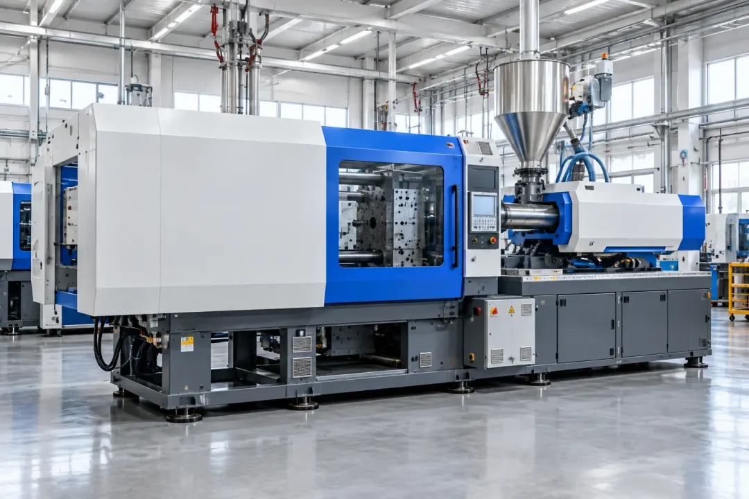
Application illustration: An injection-moulding machine inside a bright industrial production hall.
Industrial equipment

Rigid equipment frames and support structures compared at defined stationary or repeatable operating states.

Large equipment and injection-moulding machines

Static inclination of the selected machine base or frame under comparable stationary conditions.
Application illustration: An injection-moulding machine inside a bright industrial production hall.
Large equipment and injection-moulding machines

Record the inclination of a selected injection-moulding-machine base or large equipment frame at agreed stationary states. The H310-TS380C’s ±0.01° accuracy grade supports a finer angle reference around relocation, support adjustment or foundation work. Compare the same machine condition; precision levelling, dynamic vibration and production control require their own methods.
Inclination to monitor
Static inclination of the selected machine base or frame under comparable stationary conditions.
Monitoring point
Rigid points on the machine base or frame representing the required orientation.
Plan your installation
Specify levelling requirements, site temperature, operating vibration and the conditions under which readings will be compared.
Discuss this application

Heavy machine-tool bases

Static inclination of the approved machine-tool base with comparable carriage, load and thermal states.
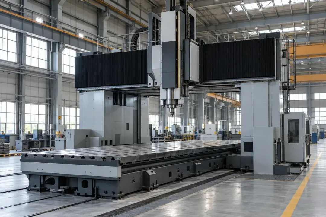
Heavy gantry machine tool with a visible structural base and factory floor.
Heavy machine-tool bases

Follow inclination at a rigid machine-tool base after it reaches an agreed stationary condition. The H310-TS380C can support a ±0.01° accuracy reference for maintenance and foundation comparisons. Record the axis convention and machine configuration, and use the maker’s metrology procedure for final levelling, spindle geometry and machining-accuracy acceptance.

Inclination to monitor
Static inclination of the approved machine-tool base with comparable carriage, load and thermal states.
Monitoring point
A manufacturer-approved rigid base location representing the selected orientation.
Plan your installation
Machine type, carriage position, load arrangement, thermal state, reference checks.
Discuss this application

Production-line frames

Slow inclination change of the selected fixed load-bearing frame under agreed stationary conditions.
Fixed production-line support frames and maintenance access inside an industrial hall.
Production-line frames

Compare local inclination at approved fixed production-line frames or stationary fixture supports. The H310-TS380C supports a finer angle reference where the task specifies ±0.01° accuracy, with loading and setup conditions documented. For adjustable workholding fixtures, compare agreed stationary settings; the one-minute acquisition profile is not a rapid motion-control signal.
Inclination to monitor
Slow inclination change of the selected fixed load-bearing frame under agreed stationary conditions.
Monitoring point
A fixed load-bearing frame member, away from moving tooling and covers.
Plan your installation
Frame or stationary fixture details, mounting point, reference position, representative loads and required local-angle accuracy.
Discuss this application

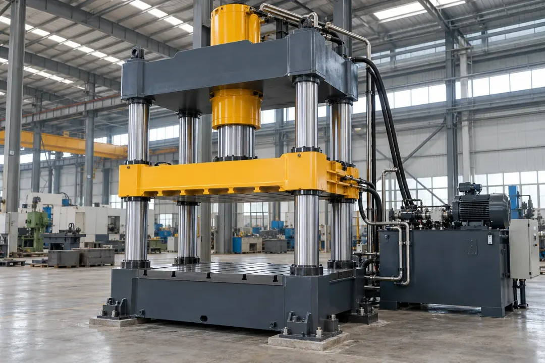
Heavy press bases

Static inclination of the approved press base or support frame in the agreed stopped state.
Large four-column industrial press with a rigid lower base and visible foundation supports.
Heavy press bases

Record local inclination at a selected press base or rigid support frame in an agreed stationary state. The H310-TS380C’s ±0.01° accuracy grade can support reference comparisons around foundation or support maintenance. Keep the machine condition and mounting reference consistent; press-stroke dynamics, vibration and machine protection remain separate functions.
Inclination to monitor
Static inclination of the approved press base or support frame in the agreed stopped state.
Monitoring point
A manufacturer-approved rigid base or support-frame surface, away from moving tooling.
Plan your installation
Identify the press type, foundation arrangement, stopped reference state, thermal conditions, permitted fixing and levelling procedure.
Discuss this application

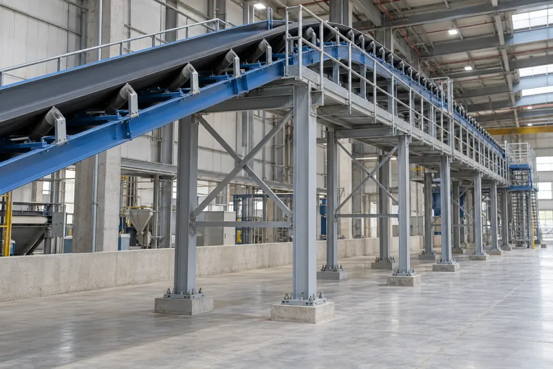
Fixed conveyor supports

Slow local inclination change of the selected fixed conveyor column or support frame.
Fixed elevated conveyor on anchored steel columns with visible bracing and maintenance access.
Fixed conveyor supports

Follow inclination at fixed conveyor columns or approved adjustable support sections once stationary. The H310-TS380C supports an agreed ±0.01° accuracy reference for installation and maintenance comparisons. Document load and adjustment states so readings describe the support structure, while conveyor tracking, belt movement and machine-safety functions remain within their dedicated systems.
Inclination to monitor
Slow local inclination change of the selected fixed conveyor column or support frame.
Monitoring point
A fixed load-bearing support column or frame, separate from moving belts and removable guards.
Plan your installation
Conveyor support geometry, stationary adjustment position, representative load, mounting clearance and required local-angle accuracy.
Discuss this application

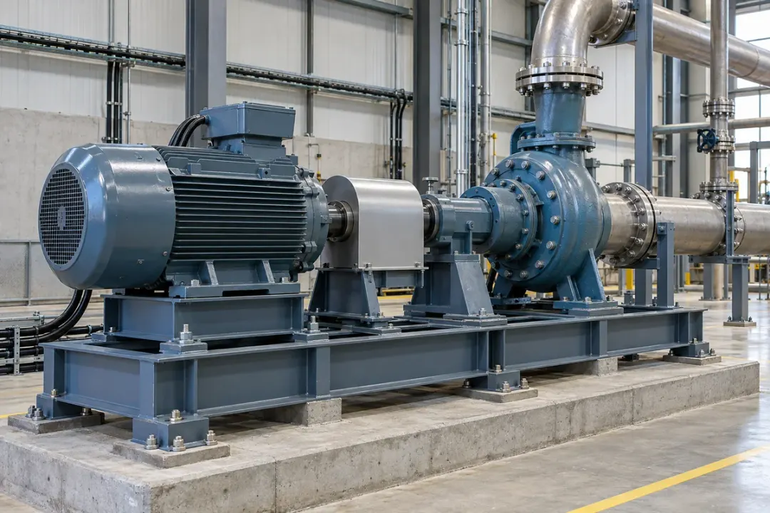
Pump-set support frames

Local inclination of an approved pump-set skid or fixed equipment-support frame at a defined reference state.
An industrial pump and motor mounted on a rigid support skid inside a plant.
Pump-set support frames

Compare local inclination at a pump-set skid or rigid equipment-test support after it is stationary. The H310-TS380C’s ±0.01° accuracy grade can support a finer mounting reference around installation, grouting or support work. Keep the pump configuration documented; shaft alignment and operating vibration require separate measurements and procedures.
Inclination to monitor
Local inclination of an approved pump-set skid or fixed equipment-support frame at a defined reference state.
Monitoring point
The approved rigid skid or support-frame location, clear of rotating parts and removable covers.
Plan your installation
Pump or equipment layout, stationary reference state, pipe loads, support work and the required local-angle accuracy.
Discuss this application
09Energy & utilities6 monitoring tasks
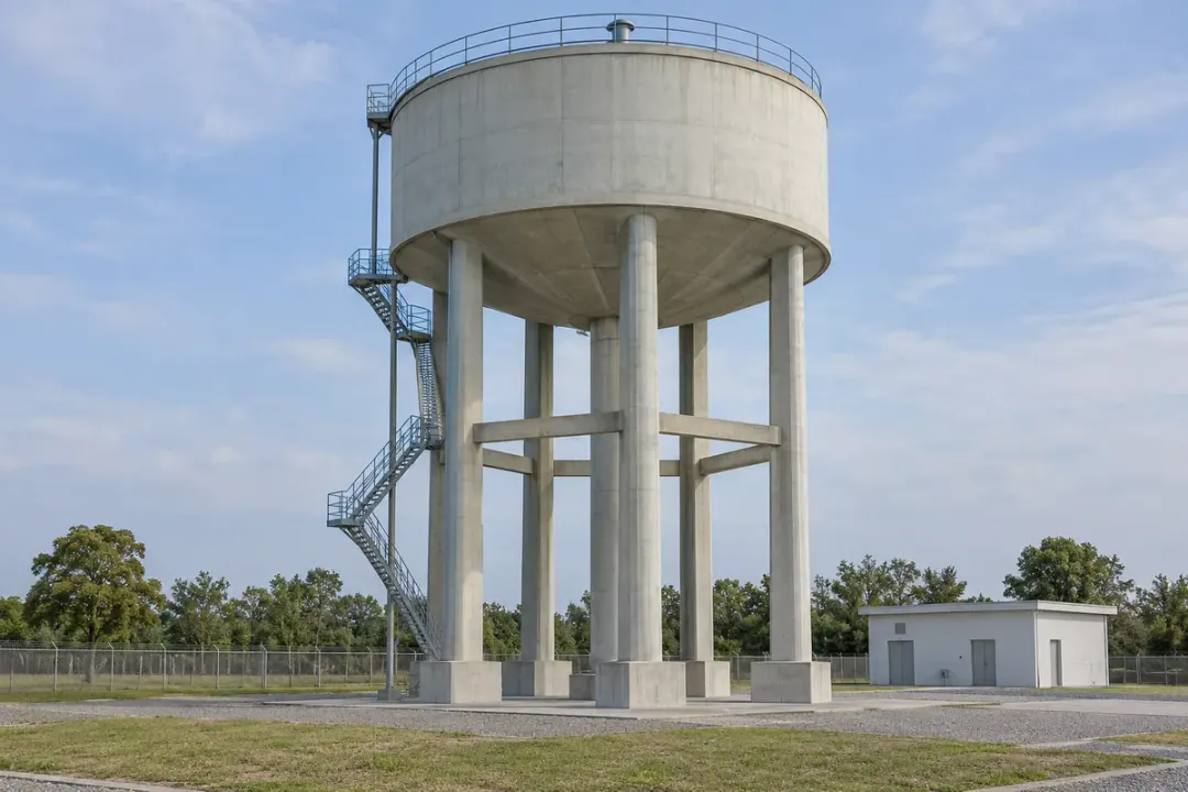
Elevated water tank with visible structural support columns.
Energy & utilities

Water, solar, storage and process-support structures, with loading, environment and the selected member recorded.

Elevated water-tank supports

Local inclination of the selected elevated-tank support member under documented loading conditions.
Elevated water tank with visible structural support columns.
Elevated water-tank supports

Follow local inclination at selected elevated-water-tank columns or rigid support members. The H310-TS380C supports a specified ±0.01° accuracy reference, with water level and the installed axis convention recorded. Compare the same support through loading and maintenance stages, using engineering inspections and separate surveys to assess the wider structure.

Inclination to monitor
Local inclination of the selected elevated-tank support member under documented loading conditions.
Monitoring point
An engineer-selected rigid support member with a documented mounting orientation.
Plan your installation
Support design, water-level records, mounting height, access, survey references.
Discuss this application

Fixed solar-panel supports

Local inclination of the selected fixed photovoltaic post or load-bearing support frame.
Fixed photovoltaic arrays with visible posts, inclined frames and ground foundations.
Fixed solar-panel supports

Record inclination at selected fixed solar-panel supports or manually adjusted frames after they are set. The H310-TS380C can support a finer angular reference where ±0.01° accuracy is specified. Document the structural member and stationary setting, keeping inclination review separate from sun tracking, compass heading and electrical-performance assessment.
Inclination to monitor
Local inclination of the selected fixed photovoltaic post or load-bearing support frame.
Monitoring point
A fixed support post or load-bearing frame representing the monitored orientation.
Plan your installation
Support member, agreed stationary or manually set position, mounting orientation, exposure and required local-angle accuracy.
Discuss this application

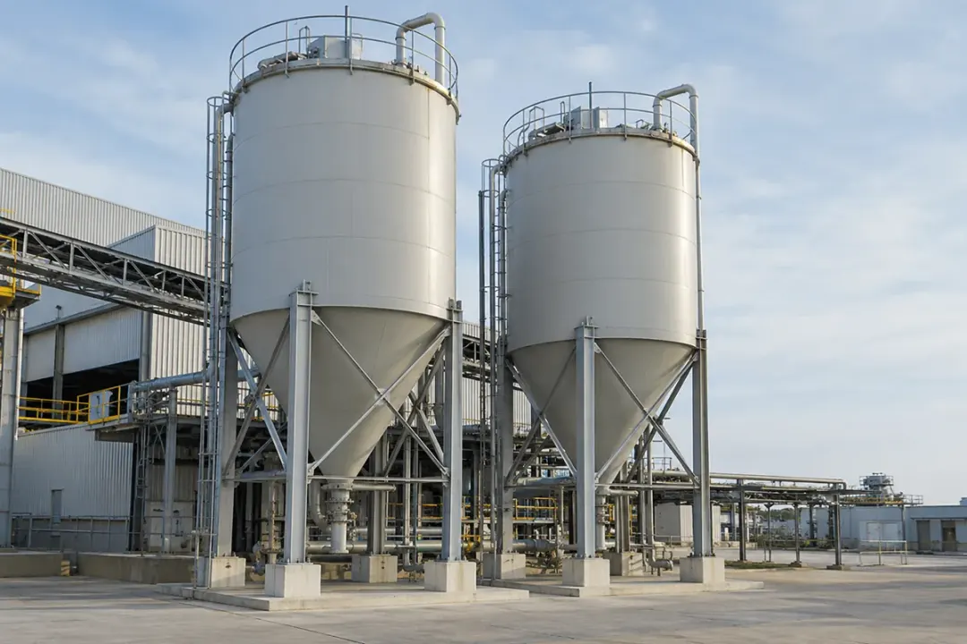
Silo & tank supports

Local inclination of the selected external support leg or frame under comparable filling conditions.
Industrial silo or tank supported by visible external legs and structural framing.
Silo & tank supports

Compare local inclination at selected silo legs or tank-support members under documented fill conditions. The H310-TS380C’s ±0.01° accuracy grade supports finer angular references where specified in the monitoring plan. Keep each point tied to its support identifier and maintenance record, with surveys and structural review addressing overall movement or capacity.
Inclination to monitor
Local inclination of the selected external support leg or frame under comparable filling conditions.
Monitoring point
An accessible engineer-approved support leg or frame outside the process boundary.
Plan your installation
Support arrangement, filling states, temperatures, area classification, fixing access.
Discuss this application

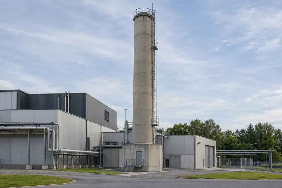
Chimney bases

Local angular change at the approved external chimney-base member within its environmental limits.
Industrial chimney and its accessible external base structure.
Chimney bases

Follow local inclination at approved chimney-base or lower structural points. The H310-TS380C supports a project specifying ±0.01° accuracy for those reference locations, with temperature, wind and operating state documented. Select a mounting environment within the device’s supplied limits; overall chimney shape, displacement and condition require complementary engineering methods.
Inclination to monitor
Local angular change at the approved external chimney-base member within its environmental limits.
Monitoring point
An approved rigid base member within the selected configuration's environmental conditions.
Plan your installation
Base design, thermal exposure, operating states, access, complementary survey.
Discuss this application

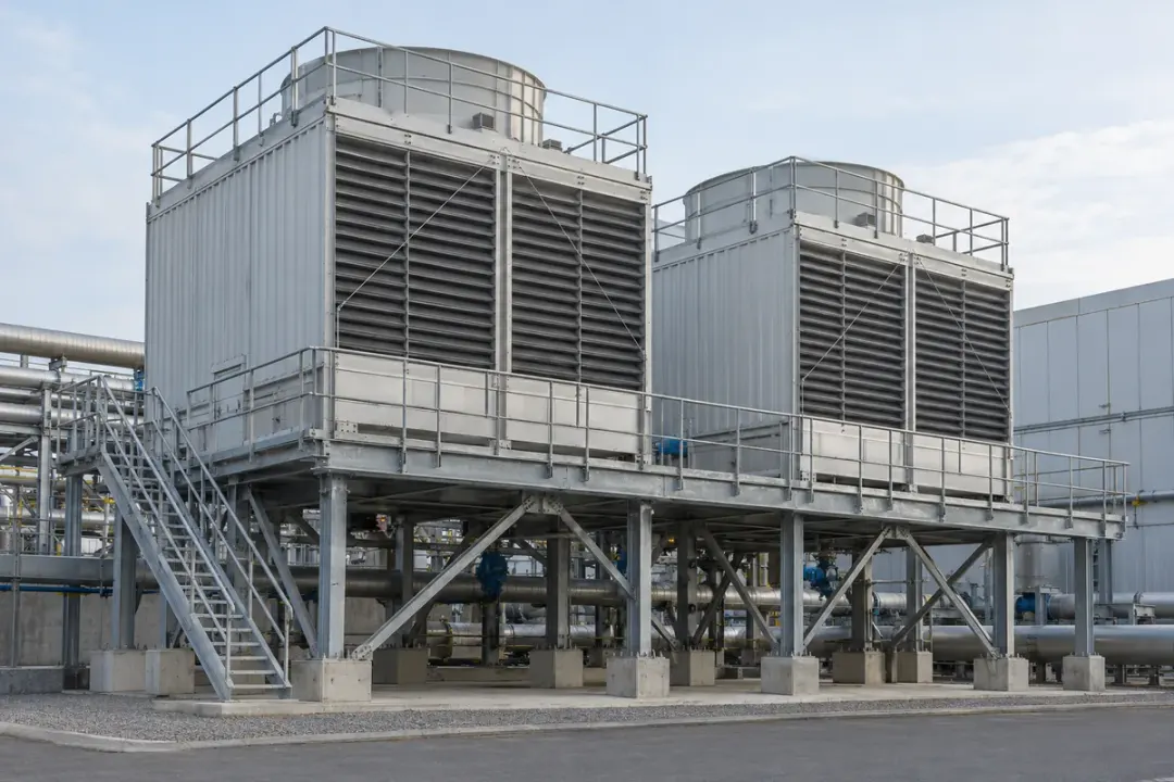
Cooling-tower supports

Local inclination of the selected fixed cooling-tower support under comparable operating states.
Industrial cooling tower mounted on a visible fixed support frame.
Cooling-tower supports

Record inclination at selected cooling-tower support frames under agreed stationary or comparable operating conditions. The H310-TS380C provides the ±0.01° accuracy grade for a defined local-angle task. Document the structural member and environment; machinery vibration, water-system performance and the condition of the overall installation need separate measurements and review.
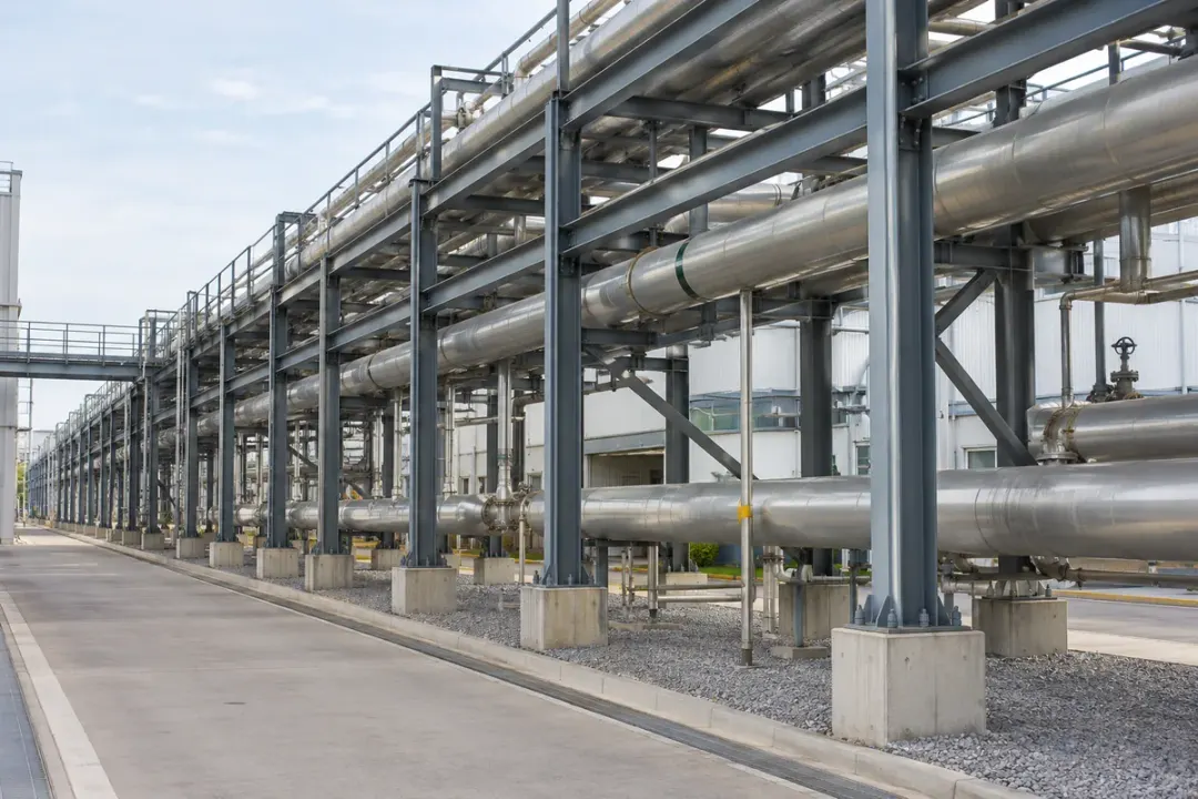
Inclination to monitor
Local inclination of the selected fixed cooling-tower support under comparable operating states.
Monitoring point
An engineer-selected fixed support, with operating disturbance assessed for the installation.
Plan your installation
Support layout, fan states, moisture exposure, loading conditions, service access.
Discuss this application

Pipe-rack columns

Local inclination of the selected fixed pipe-rack column along its documented measurement direction.
Industrial utility pipe rack with multiple service lines and visible structural columns.
Pipe-rack columns

Follow local inclination at approved pipe-rack columns carrying process or utility lines. The H310-TS380C supports finer reference comparisons where ±0.01° accuracy is specified, with loading and thermal conditions documented. Keep the fixing on the structural member; pipe strain, movement at expansion joints and hazardous-area approval require separate project checks.

Inclination to monitor
Local inclination of the selected fixed pipe-rack column along its documented measurement direction.
Monitoring point
A fixed structural column rather than a moving pipe, insulation or removable cover.
Plan your installation
Frame grid, carried services, thermal states, area classification, fixing details.
Discuss this application

SERIES & CONFIGURATIONS

The right specification.
For your installation.

Use H310-TS380C and its ±0.01° accuracy grade as the model reference. Specify the axis convention, required working range and data interface with the selected radio and enclosure.

MODEL REFERENCE

H310-TS380C

Triaxial high precision tilt sensor · ±0.01° accuracy. Technical details below follow the 2026-10-27 datasheet. Per-axis angle definitions, range, resolution and configuration conditions form part of the supplied specification.

Download H310-TS380C datasheet (EN) Select a configuration ↓
H310-TS380C — triaxial tilt sensor specification
ModelH310-TS380C
Product gradeTriaxial · high precision
Accuracy±0.01°; applicable range and test conditions follow the supplied configuration
Sensing typeMEMS; three-axis sensing (X / Y / Z)
Angle outputsAngle definitions and reference orientation follow the supplied protocol; gravity-referenced inclination does not independently determine yaw
Range & resolutionWorking range and reported increment specified per axis / ordered configuration
Acquisition interval1 minute
Scheduled reporting interval4 hours
Reference battery life10 years: 1-min acquisition, 4-hour reporting, 25°C, normal signal; varies with enabled functions, events and radio retries
Power supply19000 mAh battery; 38000 mAh option
Communication variantsLTE Cat.1 (4G); NB-IoT / LoRa by selected variant; regional bands and modem options by supplied configuration
SIM arrangementStandard IoT SIM; embedded SIM / eSIM option, for applicable cellular variants
Enclosure protectionMetal enclosure: IP68; plastic enclosure: IP66
Operating & storage temperature−40°C to +85°C
Operating humidity5% to 95% RH, non-condensing
Body size115 × 90 × 60 mm; platform body reference
InstallationWall, pole or DIN-rail mounting, by selected kit
NFC & firmware updatesNFC activation and local configuration; remote firmware updates on supported versions
Platform & interfaceHitelecom Cloud or a compatible customer platform; select the supported data interface
Certification referencesCE completed for H200/H300/H500 platform. Confirm applicability to the supplied configuration and other CCC / FCC / RoHS references.

A configuration built around your project.

01

The change you need to observe

Identify the member and the angle change that matters. Compare it with ±0.01° accuracy and define the required per-axis range and reported increment.

02

The installation conditions

Share fixing surfaces, mounting orientation, temperature, water exposure, access and the intended enclosure or mounting kit.

03

The reporting and platform route

Include the country, point count, selected network, report schedule, supported interface and any event-response requirements.

04

Your evaluation and rollout

Provide quantities, sample-test criteria, OEM / white-label needs, certificate requirements and target installation dates.

CONNECTIVITY & INTEGRATION

Your installation.
Your data destination.

Select 4G LTE, NB-IoT or LoRa by device variant. Bring the mounting plan and data requirements together before commissioning, whether you use Hitelecom Cloud or your own platform.

4G LTE / NB-IoT

For distributed locations

Triaxial sensorCellular networkYour platform

For sites spread across a region, select the cellular variant around local operator coverage, supported bands and the IoT SIM arrangement. Review signal quality at the actual mounting point before rollout.

  • Installation country, operator and regional bands
  • SIM / eSIM arrangement and antenna configuration
  • Supported platform interface and scheduled-report test
LoRa BY SELECTED VARIANT

For points across one site

Triaxial sensorsCompatible receiverYour platform

For a local radio deployment, agree the receiver, radio settings and onward data connection. Provide the site layout and expected point count so coverage and gateway placement can be evaluated.

  • Compatible receiver or gateway and radio protocol
  • Obstructions, distances and installation-point coverage
  • Message fields, timestamps and onward interface

Make every reported angle traceable.

Agree the supported angle outputs and a sample message with your platform team. Map the device and asset IDs, channel names, axis convention, units, timestamps and installation reference. Validate data from a commissioned monitoring point before expanding the deployment.

Discuss platform integration ↗

ANSWERS FOR YOUR PROJECT

Frequently
asked questions.

Practical answers for specifying, installing and integrating the H310-TS380C high precision triaxial tilt sensor.

Ask about your project ↗
What is the H310-TS380C triaxial tilt sensor?

H310-TS380C is a high precision MEMS tilt sensor with ±0.01° accuracy and X/Y/Z sensing. It measures inclination at a defined mounting point, using the angle outputs and reference orientation specified by the supplied protocol.

Typical projects include warehouse rack uprights, poles, structural members and machine frames. One-minute acquisition and four-hour scheduled reporting support remote angle records for the selected points.

Explore the specification →
When should I choose H310-TS380C instead of H310-TS350M?

Choose H310-TS380C when the project calls for the finer ±0.01° accuracy grade and the installation can support that measurement objective. H310-TS350M provides the ±0.1° triaxial alternative.

Selection also depends on range, resolution, temperature, fixing stability and test conditions. Accuracy is separate from the displayed increment and the threshold that triggers a project review.

Compare the other triaxial grade →
How does a triaxial tilt sensor differ from a two-axis model?

The triaxial version uses X/Y/Z sensing. The supplied protocol defines how those sensing axes are converted into reported angle channels and how the reference orientation is represented.

Choose the sensor around the outputs your monitoring plan needs and the mounting orientation. Three sensing axes alone do not establish three independent orientation angles or a complete 3D motion measurement.

Check the angle-output definition →
Does three-axis sensing measure yaw or compass heading?

Gravity-referenced inclination does not independently determine yaw, which is rotation about the gravity direction. X/Y/Z labels identify the sensing axes; they should not be interpreted as a compass heading measurement.

For an application that needs heading or another motion quantity, describe it explicitly so the required sensing architecture can be reviewed before selection.

Discuss the required outputs →
How do I establish a reliable installation reference?

Attach the sensor rigidly to the member whose inclination is to be monitored. Record the device ID, asset location, bracket position, axis orientation and initial angle after fixing.

Keep that reference with later readings. Recommission the reference after moving the device, changing the bracket or altering the measured member. A baseline supports comparison; it does not improve the stated accuracy.

See the measurement workflow →
What does the illustrated angle change represent?

The example compares 0.03° at installation with 0.05° later, a +0.02° change in one reported inclination channel. It illustrates reference comparison, rather than a three-axis vector or a complete 3D orientation.

These example values do not define range, resolution, a minimum detectable change or a notification threshold. Set review conditions for the real mounting point and applicable measurement performance.

Review the example reading →
What are the acquisition and scheduled-reporting intervals?

The reference profile acquires readings every minute and sends scheduled reports every four hours. This corresponds to 240 acquisition cycles between scheduled reports and six report intervals per day.

Acquisition frequency and transmission frequency are different. Agree which samples or values a report contains, any local retention, and the supported event-reporting and notification behaviour for your configuration.

Review the operating profile →
Under what conditions does the 10-year battery-life figure apply?

The datasheet gives a 10-year reference with one-minute acquisition, four-hour reporting, 25°C and normal signal conditions. The battery configuration is 19000 mAh with a 38000 mAh option.

Actual service life varies with enabled functions, event frequency and radio retries. Select the power arrangement against the installation conditions and operating profile.

Check the reference conditions →
Which enclosure and environmental limits apply?

The specified options are a metal IP68 enclosure or a plastic IP66 enclosure. Operating and storage temperature is −40°C to +85°C; operating humidity is 5% to 95% RH, non-condensing.

Select the enclosure, antenna and mounting kit for the actual exposure and access conditions. The 115 × 90 × 60 mm dimension is a platform body reference; verify the selected arrangement for installation drawings.

Review protection and mounting →
Can I choose 4G LTE, NB-IoT or LoRa?

The datasheet lists LTE Cat.1 (4G), with NB-IoT and LoRa by selected variant. Choose the configuration around the installation country, regional bands, operator or compatible receiver, and the required data route.

LoRa identifies the radio option; a LoRaWAN requirement needs explicit protocol compatibility confirmation. Confirm the supplied radio, gateway and platform combination before ordering.

Plan the connection →
Can the readings be sent to our existing platform?

Hitelecom Cloud or a compatible customer platform can be used with the supported data interface. Share your interface, authentication and asset-data requirements during the project review.

Agree a sample message that identifies the device, mounting point, channel names, axis convention, angle units, timestamps and reference. Test the complete path using the selected device configuration.

Review the data handover →
What are NFC and remote firmware updates used for?

NFC activation and local configuration support installation and commissioning. Record the final settings and installation reference before starting the monitoring programme.

Remote firmware updates are supported on selected versions. Confirm availability and the supplied device configuration, together with your platform and update workflow.

Discuss commissioning requirements →
Can one triaxial model cover racks, structures, poles and machine frames?

H310-TS380C can be evaluated for each of these mounting-point applications where ±0.01° accuracy, the supplied angle outputs and installation conditions meet the monitoring plan. The Applications section covers tasks across nine sectors, with warehouse racking first.

For racks, identify uprights and fixing points; for infrastructure, define the monitored member with the responsible engineer. Machine-frame inclination is a static or settled-position task. Minute-interval tilt readings do not specify dynamic vibration, rapid motion or machinery alignment performance.

Explore the application tasks →
What information is needed for a quotation or OEM project?

Include H310-TS380C, the installation country, quantities, application and rollout date. Share a site photograph or drawing, mounting orientation, required per-axis range, useful angle change and expected environment.

Add the selected network, platform interface, reporting and event-response requirements, sample acceptance criteria and any OEM / white-label needs. CE is completed for the H200/H300/H500 platform; confirm certificate applicability and other requested compliance references for the supplied configuration.

Prepare your project brief →

LET'S TALK ABOUT YOUR PROJECT

Your next step.
A sensor that fits.

Tell us about your H310-TS380C application. We’ll help match the accuracy grade, reported axes, mounting and data route to your monitoring plan.

sales@hitelecom.cn ↗

Start with three details.

Your application, installation country and estimated quantity. Add a site photo or platform requirements to your email when available.

PROJECT ENQUIRY

Let’s find your configuration.

H310-TS380C · ±0.01° · triaxial inclination

Review your brief, then send it with your email app.

Discuss your project