


A defined ±0.1° accuracy grade
Select H310-TS150M when the required inclination change is compatible with ±0.1° accuracy. Specify the working range and measurement conditions.

The Hitelecom H310-TS150M is a medium-precision tilt sensor with ±0.1° accuracy for measuring inclination at a defined mounting point. Explore rack uprights, poles, equipment frames and other assets where this accuracy grade matches the required angle change. Start with the smallest useful change, then specify mounting, reporting and the data connection for your project.
KEY FEATURES
Match the accuracy grade, measured element and installation to the angle change your team needs to review.
Select H310-TS150M when the required inclination change is compatible with ±0.1° accuracy. Specify the working range and measurement conditions.
Associate the mounting point with a rack bay, pole, frame or equipment ID so the reading has a clear location in the inspection record.
Record the initial position after fixing the sensor. Review later readings using the same mounting position and angle convention.
Choose the measured member, fixing surface and access together. Share drawings or a site photograph to define the installation arrangement.
Include your communication and platform requirements in the enquiry. Confirm the supported configuration and interface for the supplied model.
Define a project-specific review condition and the person who will assess a persistent change. Validate the complete workflow during commissioning.
A CLEARER VIEW OF CHANGE
A tilt sensor measures the angle at its own mounting point. For H310-TS150M, compare later readings with a documented installation reference and assess the useful change against the ±0.1° accuracy grade. The asset, fixing arrangement and site conditions give that trend its meaning; the angle reading describes local rotation at the chosen point.
Find your applicationIllustrative comparison only. Specify the supplied working range and resolution separately.
Fix the sensor to the selected element. Record its asset ID, mounting position, angle convention and initial reading.
Compare the project’s smallest meaningful change with ±0.1° accuracy, then specify the range, reading interval and review condition.
Confirm the supplied data interface, identify the responsible team and test the agreed reporting workflow during commissioning.
CHOOSE YOUR MEASUREMENT GRADE
H310-TS150M is the ±0.1° medium-precision option. Compare the required angle change with the grade before selecting the mounting, operating profile and data route. H310-TS150M acquires an angle reading every minute and sends scheduled reports every four hours, with 240 acquisition cycles between reports.
Existing high-precision tilt sensor entry.
H310-TS150M accuracy grade.
H310-TS100L accuracy grade.
Required angle change, mounting and measurement conditions.
Accuracy, resolution and a project review threshold describe different things. Specify them separately for the working range and site conditions. Confirm the measurement and reporting intervals, power arrangement and enclosure for the supplied H310-TS150M configuration.
APPLICATIONS
Explore inclination records for warehouse racking, infrastructure, industrial equipment and energy assets. Each task identifies the measured member, mounting point and project details for the ±0.1° model.
9 industry categories 39 monitoring tasks
Application illustrations show monitoring environments; they are not customer installation records.

Rack systems, automated high-bay storage and mezzanine columns across the warehouse.
Keep an inclination history for selected pallet-rack uprights across the warehouse. Link each reading to the rack row and bay, then compare it with the installation reference, documented load states and handling reports. The record gives the warehouse team a consistent way to review orientation after layout changes, reported forklift contact or rack maintenance alongside its normal inspection process.
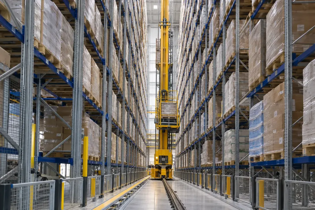
Connect local upright-orientation readings to the rack rows and service locations of an automated high-bay warehouse. Maintenance teams can compare the angle history before and after stacker-crane servicing, rack adjustments or reported contact, using consistent loading conditions. The named monitoring points keep the information useful across a large storage installation while leaving crane, shuttle and load clearances available.
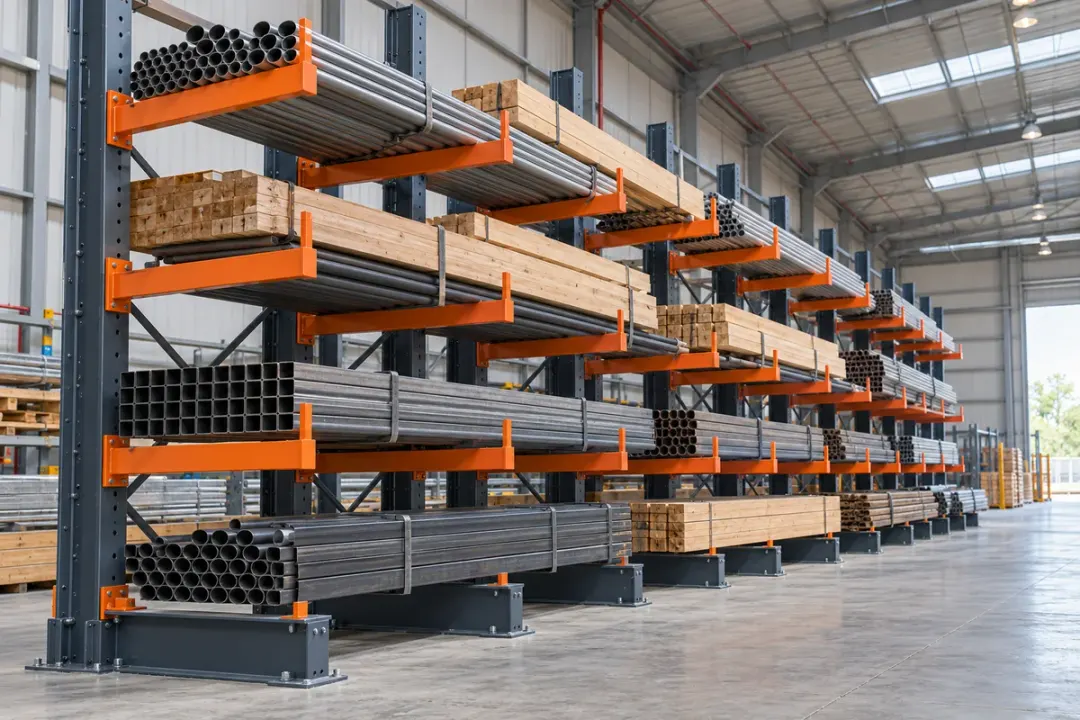
Follow the orientation of selected cantilever-rack columns carrying tubes, timber or other long goods. Associate each point with its bay, arm arrangement and normal load distribution so later readings can be compared meaningfully. The resulting angle record supports review after handling impacts, rack adjustments or changes in stored lengths and weights, with the required sensitivity defined for the installation.

Organize upright-inclination records by storage lane in drive-in or drive-through pallet racks. Compare readings with the installation reference and documented loading sequences to review changes after reported forklift contact, support-rail adjustment or maintenance. Recording the same structural member under comparable loads helps the inspection team relate an angle change to a specific lane rather than an unidentified part of the warehouse.
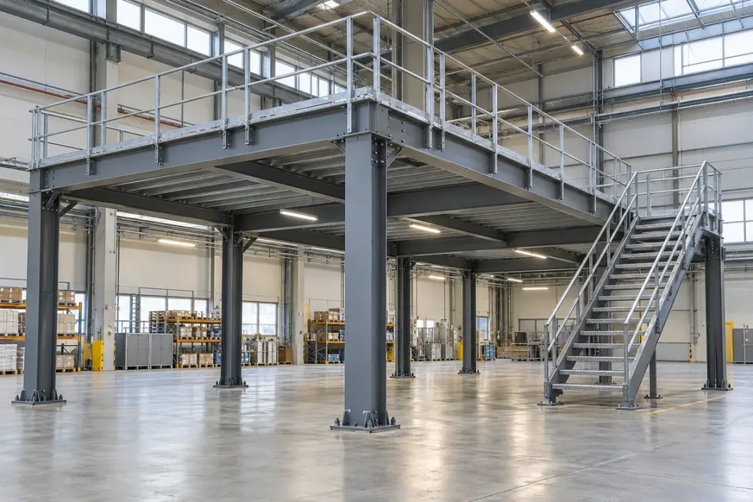
Associate inclination readings with the columns supporting a warehouse mezzanine or storage platform. Establish the reference after installation and record representative loads on the level above. Later comparisons provide an orientation history for review after storage-layout changes, equipment relocation or support maintenance, keeping each reading linked to the column grid and the owner’s inspection records.

Street lighting, power lines, telecom sites and roadside sign supports.
Keep a named inclination reference for street-light poles across roads and public spaces. Maintenance teams can compare later readings after reported vehicle contact, foundation works or pole servicing, with each record tied to the same fixing direction and asset identifier. The approach also applies to selected roadside equipment poles where a local orientation history is useful for planned inspection and maintenance.
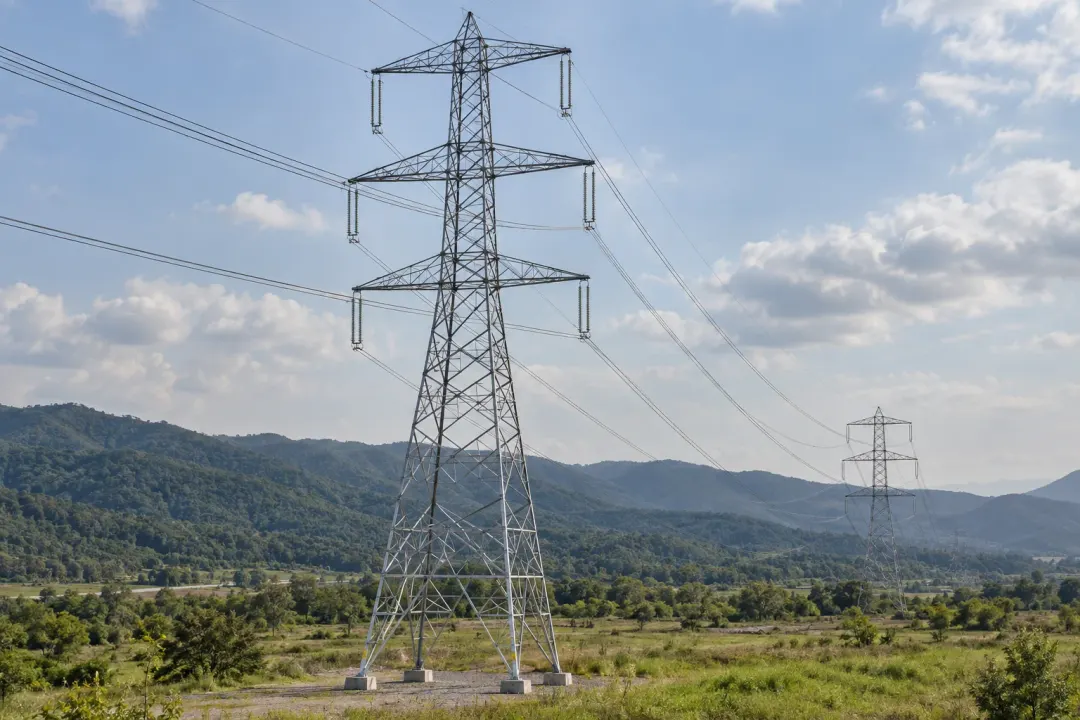
Relate orientation readings from selected transmission-tower members to the tower identifier, mounting level and measurement direction. A documented reference supports comparisons after foundation works, member replacement or scheduled inspections. Keeping the angle history with maintenance and site-condition records helps the utility review a persistent local change at the intended member, using the angular sensitivity specified in its asset monitoring plan.
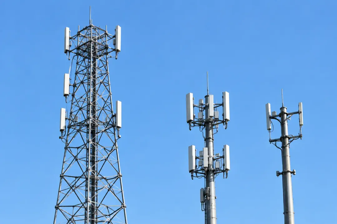
Maintain a local orientation history for selected telecom-tower members as equipment and site arrangements change. Link every point to its mounting height, measurement direction and tower reference, then compare readings with antenna additions, maintenance visits and foundation inspections. The record helps the site team distinguish a persistent change at a named structural member from an undocumented change in the measurement setup.

Connect the inclination history of a billboard support pole to the sign location and its maintenance record. Compare the same member and measurement direction after panel replacement, support work or foundation servicing, noting the relevant wind and loading conditions. This gives the sign owner a repeatable local angle reference for inspection review without confusing changes in the billboard panel with changes in its support.
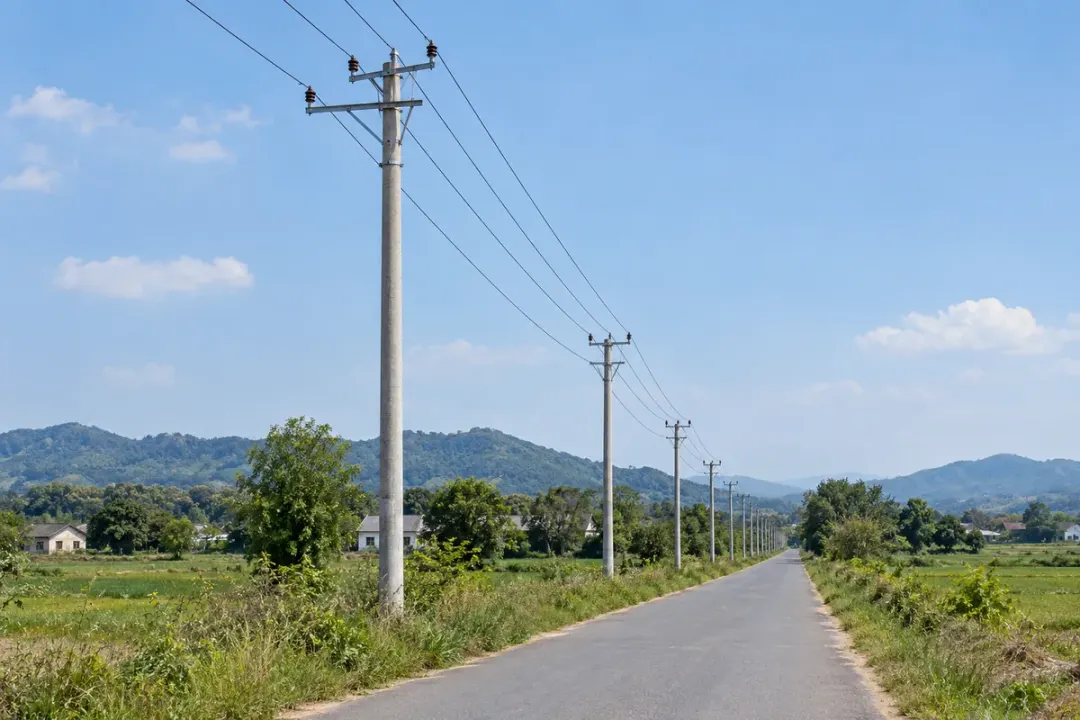
Organize inclination records for selected distribution poles by asset number and line section. Compare the local pole angle with its installation reference after nearby ground works, pole maintenance or reported contact, using the same measurement direction. A consistent point record gives the utility team useful context for field inspections across dispersed routes and helps connect an observed change to the correct pole.

Selected bridge members, highway retaining walls and working waterfront structures.
Keep an angle record for a named bridge pier or other selected rigid member during agreed installation, maintenance or inspection stages. Connect each reading to its fixing direction, reference condition and relevant work records. H310-TS150M is an option where the engineering team’s local rotation objective is compatible with ±0.1° accuracy; the record complements the bridge’s established survey and inspection measurements.
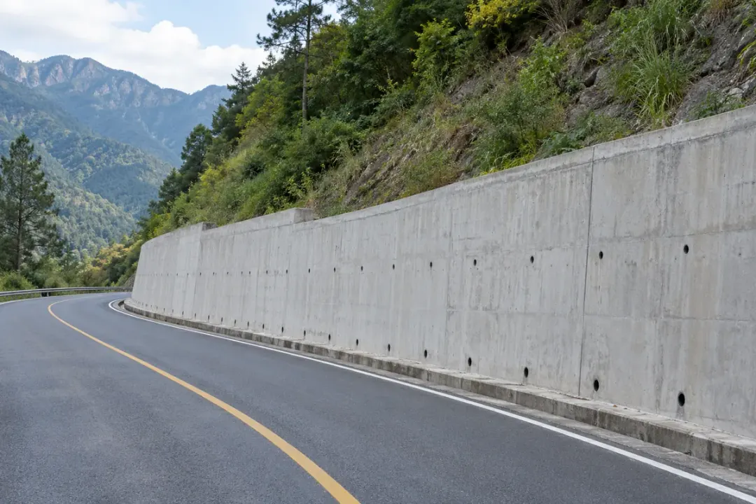
Follow the orientation of selected retaining-wall sections along a road corridor. Give each point a wall-section and elevation reference, then compare readings with drainage maintenance, adjacent excavation and inspection observations. The local angle history helps the road-maintenance team review changes at a specific section under documented conditions, with the useful angular sensitivity defined in the wall’s monitoring and maintenance plan.
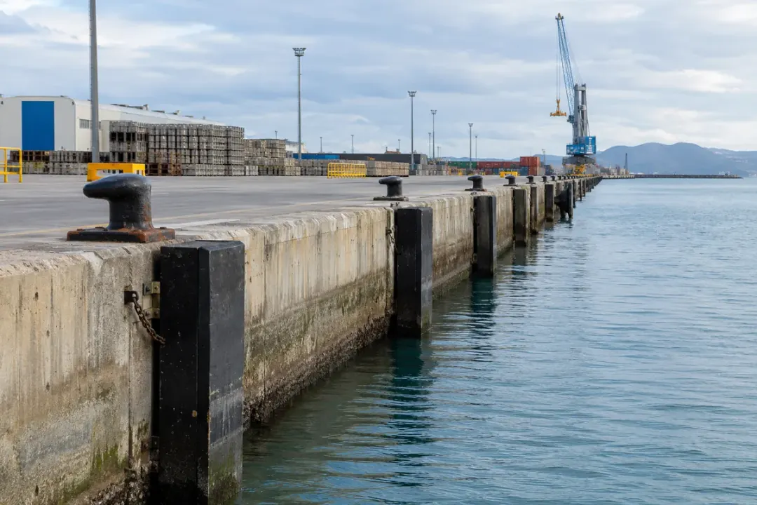
Connect local quay-wall inclination readings to a named berth section and its maintenance history. Compare the angle record with inspections, apron works and documented operating conditions, including relevant tide and loading context. A stable mounting reference helps the port team review a persistent orientation change at the intended wall element while keeping the information separate from movements of fenders, bollards or handling equipment.
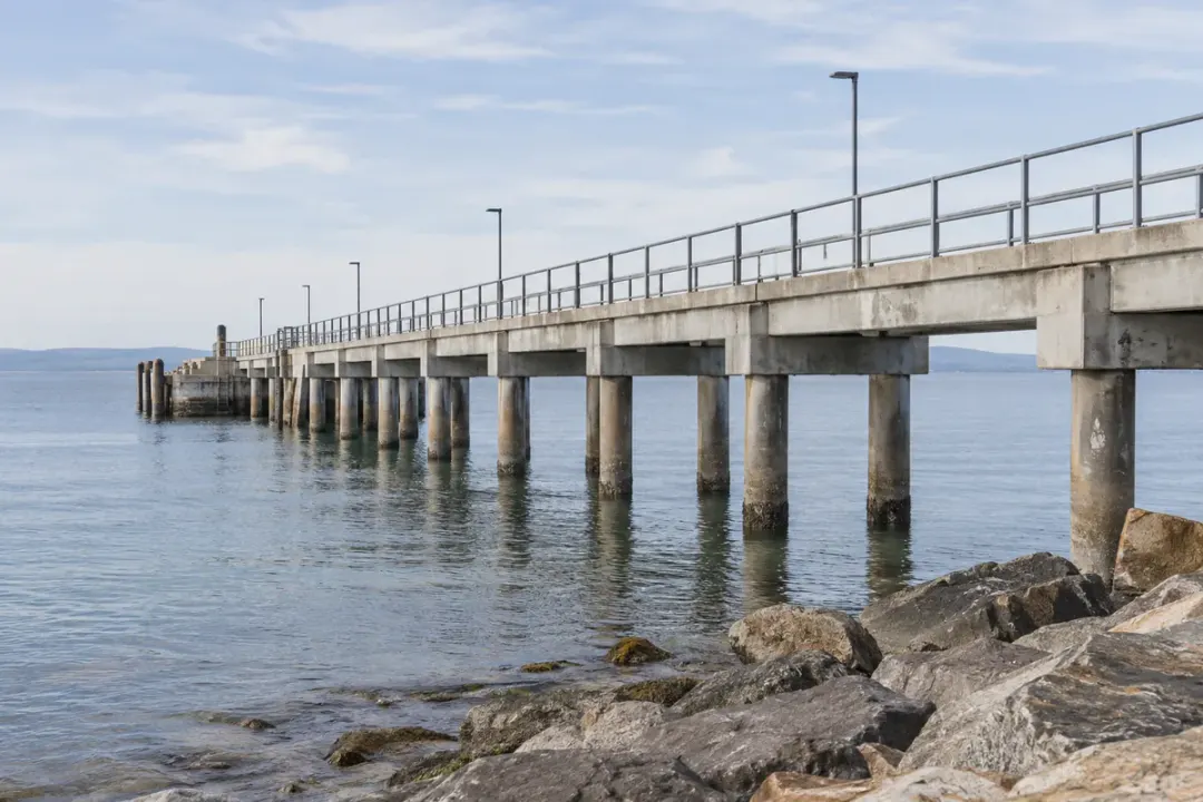
Maintain a local orientation record for selected fixed piles or support members beneath a jetty. Identify the member and measurement direction so readings can be reviewed with berth activity, repairs and scheduled structural inspections. Comparisons under agreed conditions help the owner follow a persistent change at that support, with the angle sensitivity and water-exposure conditions specified for the actual installation.
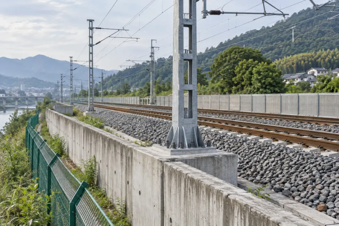
Railway-side structures, tunnel lining sections and tunnel-portal walls.
Keep inclination records for selected catenary masts or retaining-wall members beside a railway corridor. Associate each point with the asset identifier, mounting direction and installation reference, then compare readings after authorized maintenance or nearby works. This supports review of the named structural member where ±0.1° accuracy matches the specified angle task, alongside the infrastructure owner’s inspection and survey procedures.
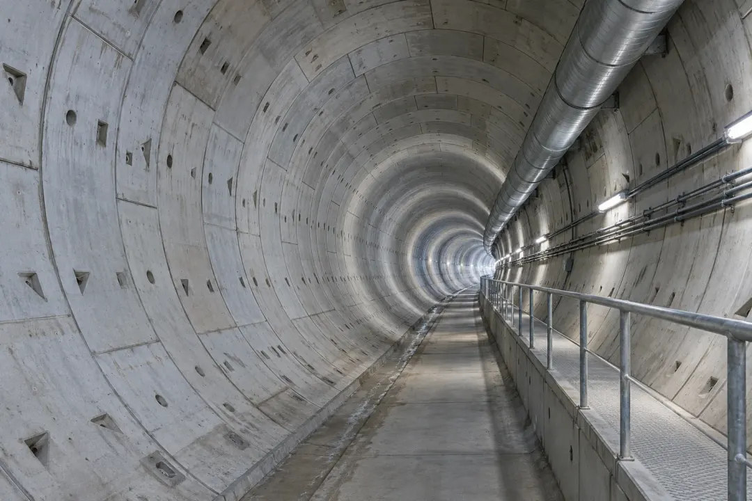
Tie a local inclination record to a selected concrete tunnel-lining section and its documented reference direction. Compare readings at agreed project stages with lining inspections, adjacent works and maintenance records. This provides an additional angle history for the named section when the required local rotation measurement fits ±0.1° accuracy, with interpretation kept within the tunnel engineer’s wider survey and monitoring plan.
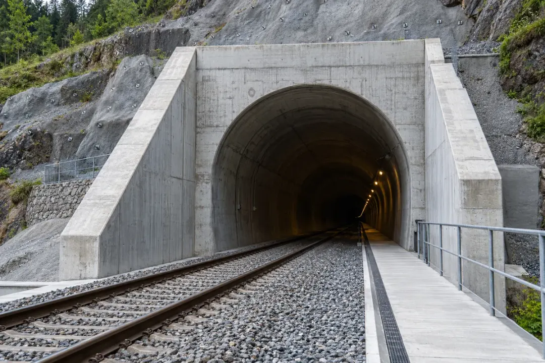
Follow local orientation at selected concrete headwall or sidewall sections around a tunnel portal. Keep the section identity and fixing direction with the installation reference, then compare readings after portal works, drainage maintenance or nearby excavation. The angle history gives the project team a defined structural point to review alongside visual inspections and other site measurements at the tunnel entrance.
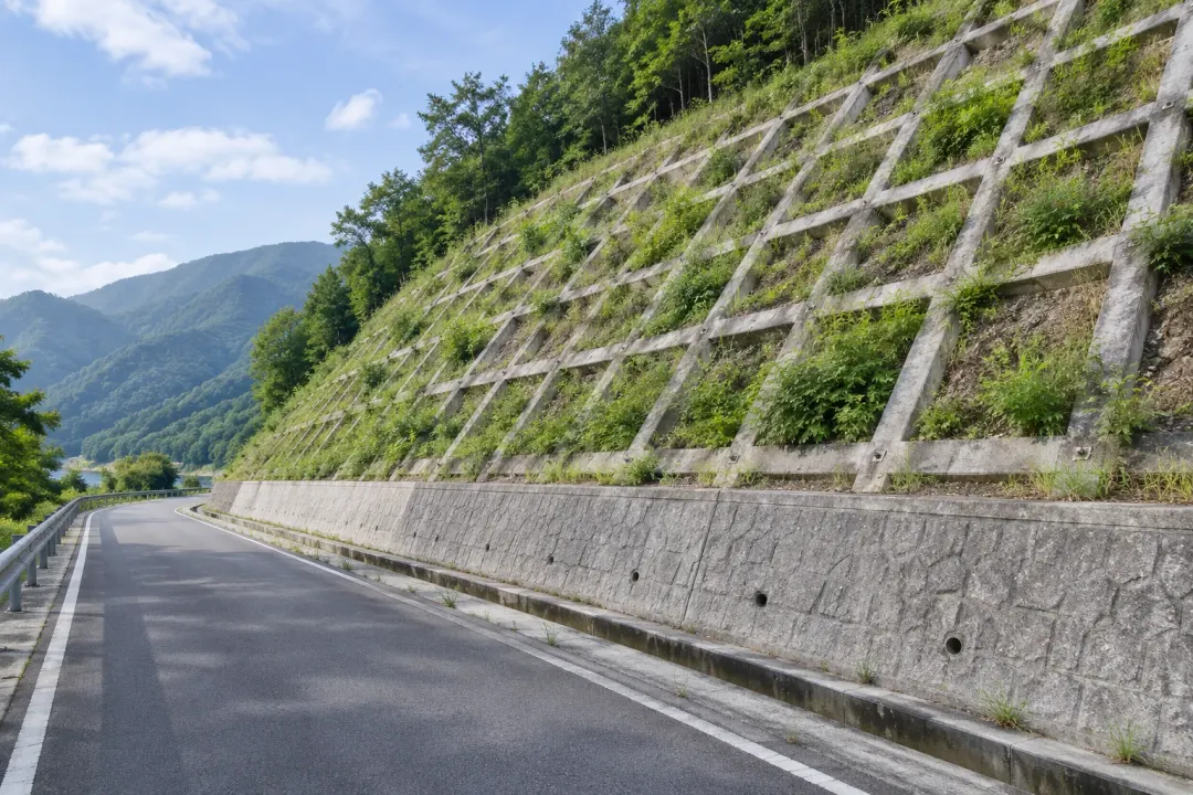
Engineered slopes, concrete-dam sections, mine benches and reservoir-bank retaining structures.
Follow local inclination at selected rigid retaining or stabilization members on an engineered slope. Link each point to its structural section and initial reference, then compare readings with drainage work, inspections and changes to the adjoining ground. The angle history adds a named surface-structure record to the site plan where the required angular sensitivity matches the medium-precision grade.
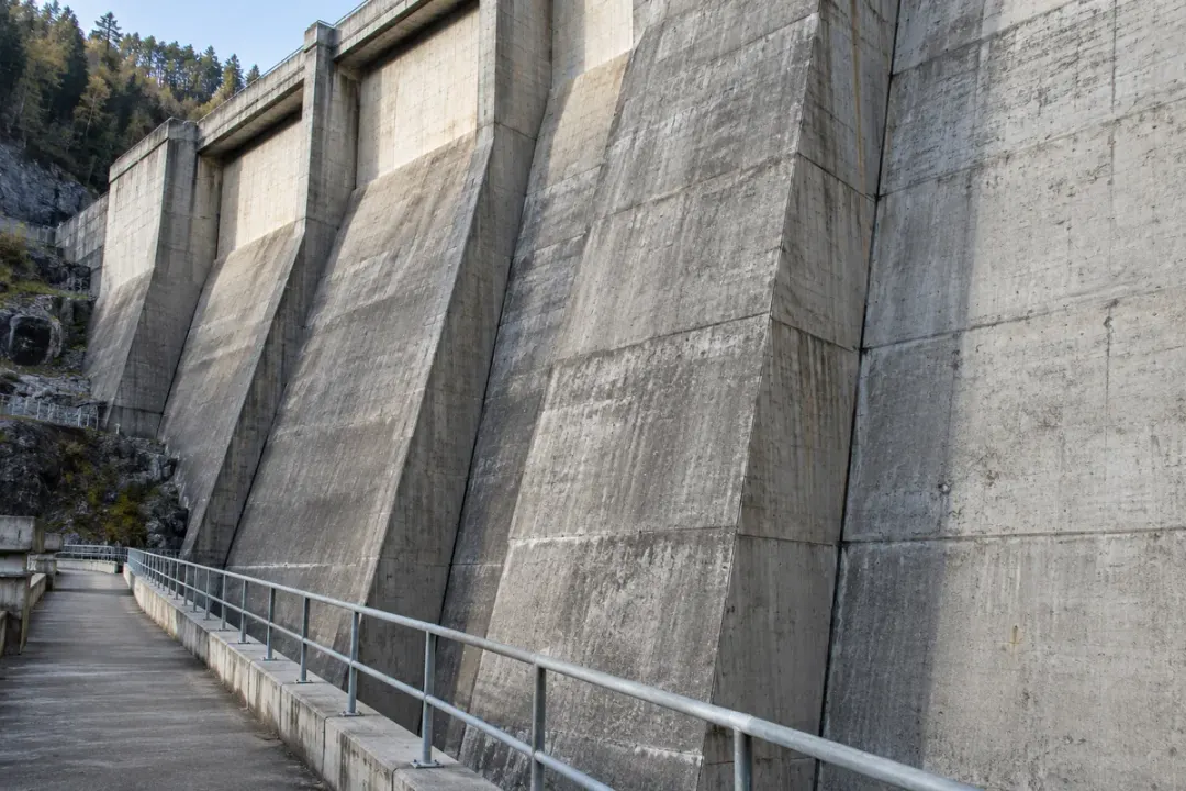
Maintain a local angle record at an engineer-selected concrete dam section, with the block identity, fixing direction and reference conditions documented. Compare readings at agreed inspection or maintenance stages with the dam’s existing measurement records and water-level context. Use the ±0.1° grade only when it suits that defined rotation task; this point record remains one input to the owner’s wider monitoring programme.
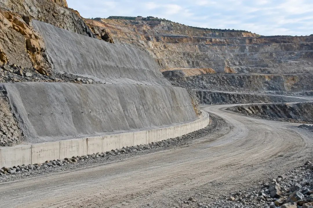
Keep an orientation history for selected rigid retaining or concrete facing sections beside an open-pit bench road. Identify the bench, member and reference direction so comparisons remain tied to the same structural point. The mine team can review the angle record with excavation stages, drainage works and inspections, using the sensitivity and interpretation defined in its geotechnical monitoring plan.
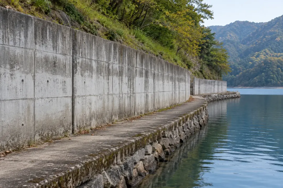
Associate local inclination readings with named retaining-wall sections along a reservoir bank. Compare the same point and direction with its installation reference, recording water-level context, drainage maintenance and nearby works. The resulting angle history helps the owner review a persistent change at a specific wall section while maintaining a clear link to the shoreline inspection and maintenance record.
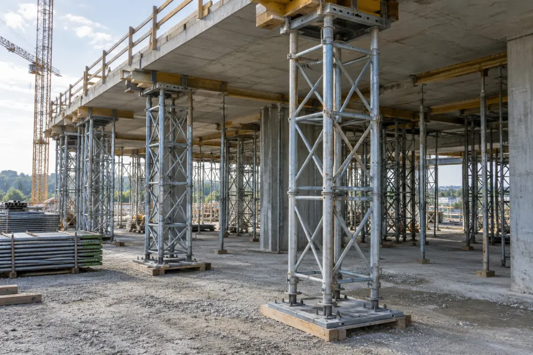
Temporary support systems, excavation walls, steel erection and modular-unit setup.
Record the orientation of selected shoring towers, falsework or temporary support members at agreed construction stages. Connect each reading to the member identifier, bracing state and reference established after installation. The angle history helps the site team compare conditions during staged loading or support changes and maintain a consistent record alongside the temporary-works inspection and measurement procedure.
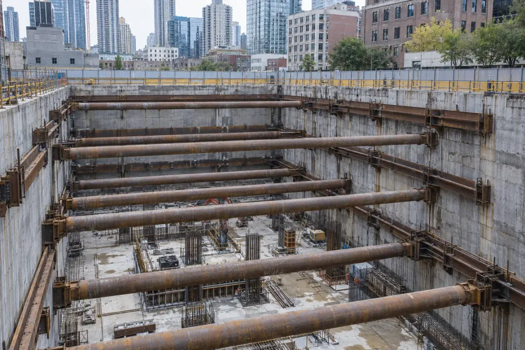
Link local wall-inclination records to the section, elevation and excavation stage of a construction project. Compare readings with the reference condition, support changes and inspection observations as work progresses. A consistent point record helps the project team relate an angle change to the documented work sequence, using the sensitivity and review process established in the excavation’s wider monitoring plan.
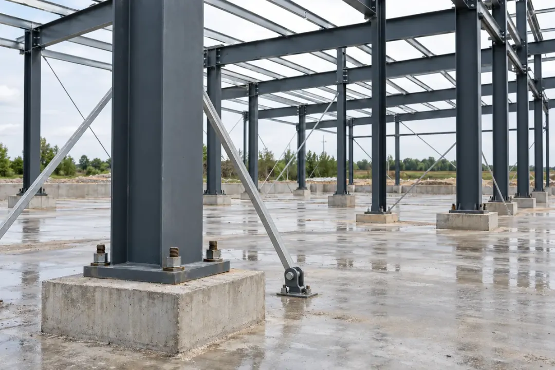
Keep a local angle record for selected steel columns during defined erection and adjustment stages. Tie each reading to the column mark, fixing direction and current bracing arrangement, then compare it with the agreed installation reference. The record supports the site’s established setting-out and inspection procedure where ±0.1° accuracy meets the specified angular task, including documented updates after intentional column adjustment.
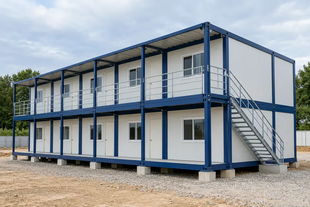
Establish an inclination reference for a selected frame member after a modular building is positioned on its supports. Identify the unit and measurement point, then compare readings after relocation, support adjustment or planned maintenance. The local angle record gives the site team consistent setup information across moves, with the normal loading condition and required angular sensitivity agreed for that unit.

Conservation projects, existing buildings under repair and the static orientation of selected trees.
Keep an orientation history for selected structural members in a heritage building or pagoda. Associate each point with the conservation survey and compare readings before and after repair, support adjustment or changes in documented loading. The record gives the conservation team a repeatable local angle reference where its required sensitivity suits the grade, using an approved fixing method that respects the historic fabric.
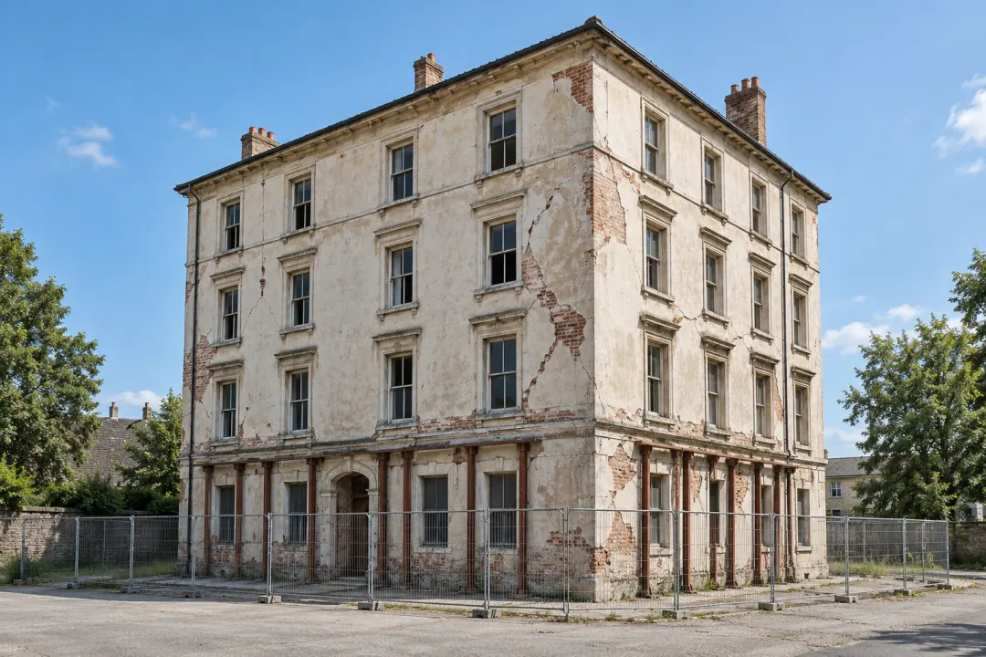
Record local orientation at building members selected for a repair or adjacent-works monitoring project. Link each point to the structural survey and a documented reference, then compare readings with the work sequence, loading changes and inspections. This keeps an identifiable angle history available to the responsible engineer as one part of the building’s assessment and maintenance records.

Keep a static trunk-orientation record for selected urban or heritage trees using an arborist-approved mounting arrangement. Identify the tree, mounting height and reference direction, then compare readings under agreed observation conditions after support adjustment, nearby works or maintenance. The angle history can accompany arboricultural inspections, with the useful angular change, growth allowance and care of the monitored tree defined in advance.
Factory equipment and fixed frames, complemented by settled-angle checks on adjustable machinery.
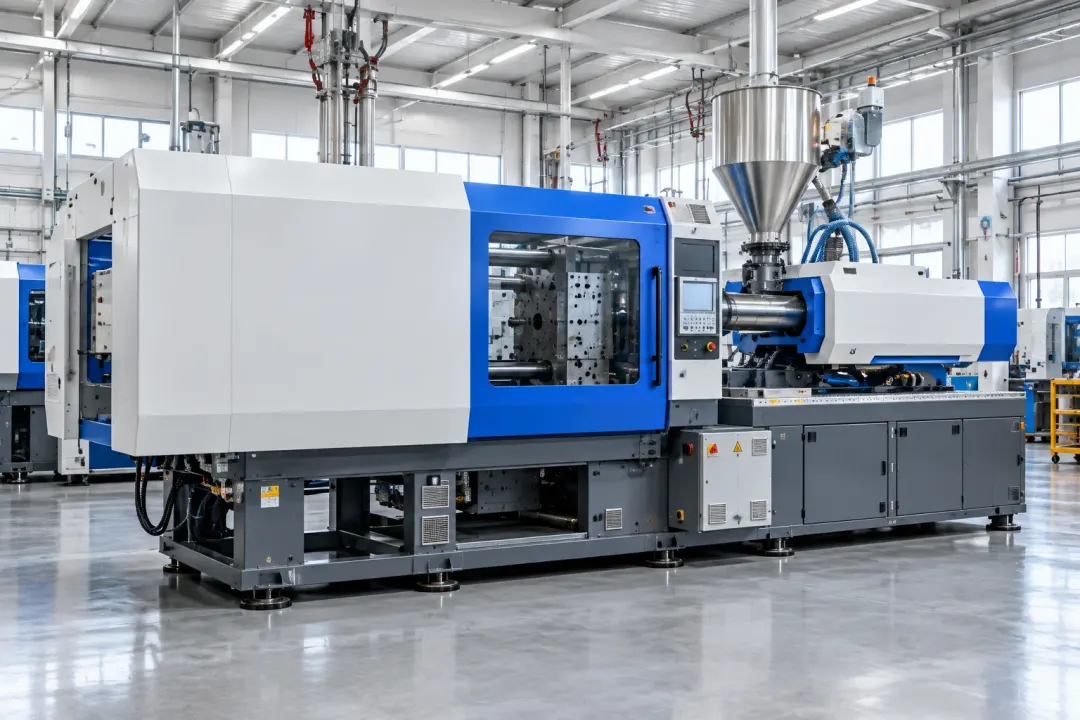
Maintain a static orientation reference for the rigid frame or base of a large machine, including injection-moulding equipment. Compare readings after relocation, foundation work or support maintenance, using the same stationary load condition. The record helps the maintenance team document a change in machine setup where the manufacturer’s required angular tolerance is compatible with ±0.1° accuracy.

Organize stationary inclination readings by frame and production-line section. Compare the same structural point after layout alterations, foundation work or support maintenance, keeping the installation reference and load condition with the record. This gives the factory team a consistent angle history for fixed frames across a large line and helps connect a reported change to the relevant maintenance activity.
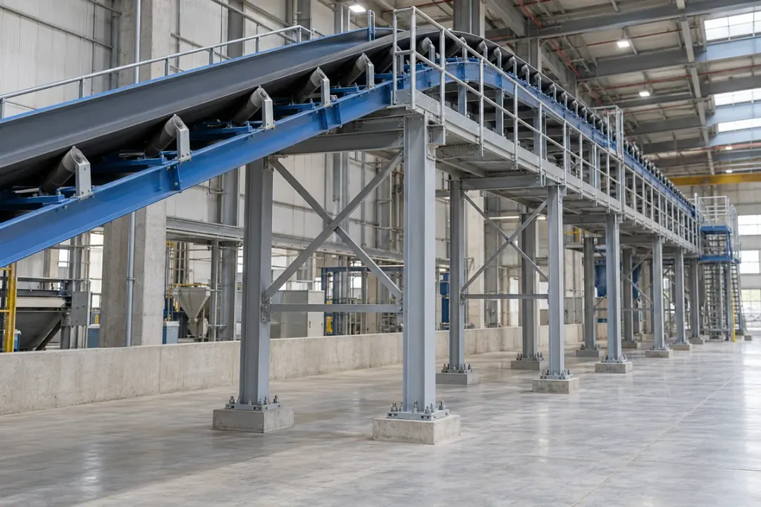
Keep a local orientation record for selected fixed supports beneath an industrial conveyor. Identify each point by support number and conveyor section, then compare readings after foundation repairs, loading changes or maintenance under agreed stationary conditions. The record helps the maintenance team review the intended support member separately from belt movement, roller adjustment or changes elsewhere along the conveying route.
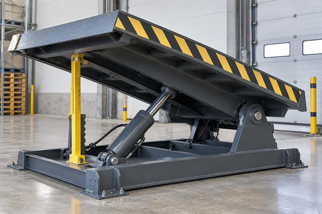
Record the settled inclination of a pallet-tilting platform at the positions used in a handling process. Mount the sensor on the moving platform member and identify the loading condition for each comparison. The medium-precision grade can be specified where the required angle-setting or verification tolerance calls for a finer record than broad raised-and-lowered status.
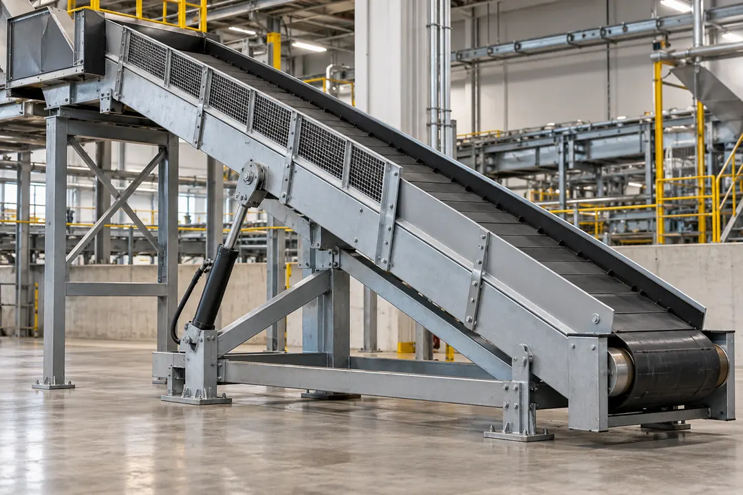
Keep an angle record for a conveyor section that is intentionally adjusted between process setups. Take the comparison after the section is secured and movement has settled, using the same reference direction. Define the permitted angular setting and required tolerance so the supplied measurement grade, working range and reporting arrangement can be matched to the installation.
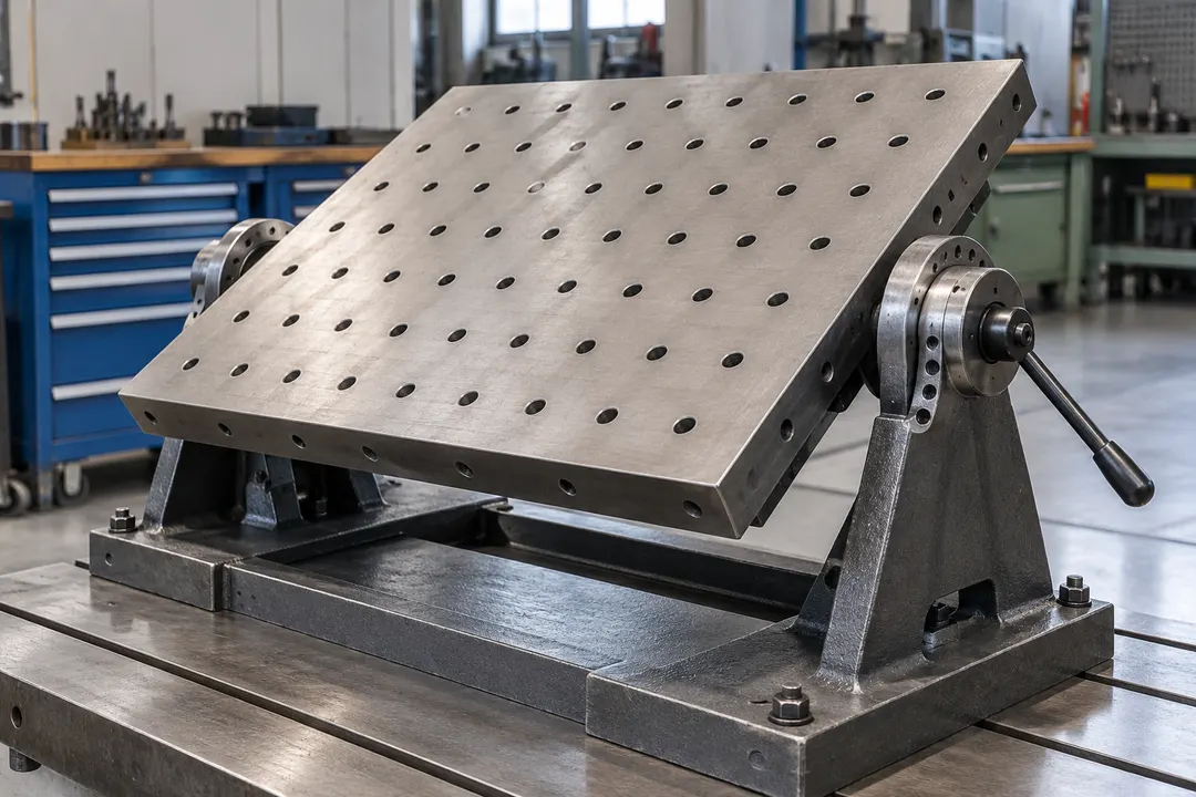
Use a repeatable inclination record when an assembly fixture is set to different working angles. Fix the sensor to the tilting fixture member and compare readings only after the position is clamped and settled. Share the required angle-setting tolerance and working positions so H310-TS150M can be assessed for this specific setup and verification task.
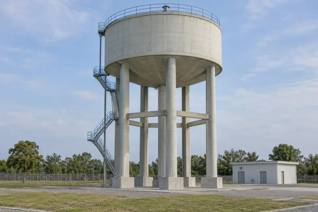
Water-tank and silo supports, solar installations and industrial pipe-rack columns.
Link inclination readings from selected water-tank support columns to the support identifier and installation reference. Compare measurements at documented water levels and review the angle history with maintenance and inspection records. Keeping the load context with each comparison gives the water-utility team a consistent local orientation record for the intended support, with the required sensitivity specified in the asset monitoring plan.

Keep an orientation reference for selected posts or frame members in a fixed solar array. Identify the row and support so readings can be compared after footing works, frame repairs or changes to the surrounding ground. The angle history helps the site team review the same rigid support over time, keeping its condition separate from panel-surface observations or an adjustable panel’s chosen working angle.
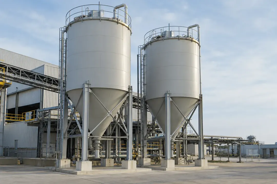
Maintain an inclination history for selected support legs or frame members beneath a silo or tank. Link each point to the support identifier and commissioning reference, then compare readings under documented fill conditions after maintenance, load changes or foundation work. The record gives the asset team a consistent local angle reference for support inspections and helps preserve the loading context behind each comparison.
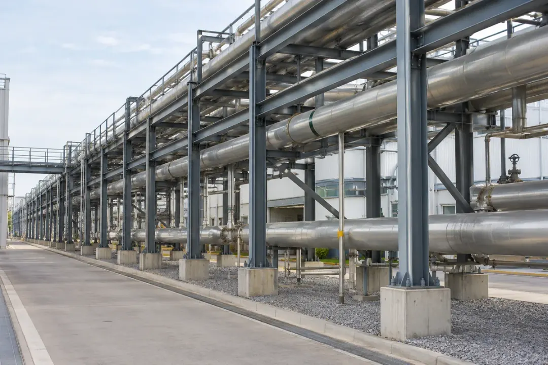
Connect local column-inclination readings to the structural grid of an industrial pipe rack. Compare the same member and reference direction after pipe modifications, support maintenance or foundation works, recording the relevant operating and load conditions. This provides the plant team with an identifiable angle history for a fixed column alongside its established pipe-support inspection and maintenance records.

Record the inclination of a solar panel or small array after its mounting angle is manually adjusted and secured. Compare the stationary reading with the project’s specified setting, keeping the same panel-frame mounting point and angle convention. Provide the required setting tolerance, site exposure and working range so the measurement configuration can be matched to the installation.
SERIES & CONFIGURATIONS
Use H310-TS150M as the model reference and ±0.1° as the confirmed accuracy grade. Include the remaining operating and integration requirements in your project brief.
Medium precision tilt sensor · ±0.1° accuracy. The quotation and supplied specification identify the working range, resolution, power, enclosure and communication configuration for your project.
Download the H310-TS150M datasheet (PDF) Select a configuration ↓| Model | H310-TS150M |
|---|---|
| Product grade | Medium precision |
| Accuracy | ±0.1° |
| Measurement | Inclination / angular position at the mounting point |
| Application focus | Local inclination trends where ±0.1° accuracy meets the monitoring objective |
| Installation reference | Record the initial position, asset ID and angle convention during commissioning |
| Acquisition interval | Every 1 minute |
| Scheduled reporting | Every 4 hours |
| Acquisition cycles | 240 per scheduled report |
| Service life | Follows the supplied configuration and operating conditions |
| Range & resolution | Specify the required working range and reported increment for the quotation |
| Reporting & integration | Confirm the supplied interface, data destination and event-reporting workflow |
| Power & enclosure | Select for the installation environment and required service arrangement |
Identify the asset or moving component, expected positions, working angle range and smallest change that matters to your team.
Share the country, site temperatures, exposure, mounting surface and access for installation or maintenance.
Define the reporting schedule, data destination, review condition and person responsible for the next action.
Include quantities, sample evaluation, OEM or branding requirements, interface details and the intended rollout date.
CONNECTIVITY & INTEGRATION
Include the required data route in your project brief. Confirm the communication configuration and supported interface for the supplied model before deployment.
If the project calls for a cellular connection, provide the installation country, operator coverage and required report schedule. Confirm the available device configuration, regional bands, SIM arrangement and platform interface for this model with the quotation.
If your site uses a local receiver or gateway, share its protocol and interface requirements. Agree the compatible device configuration, radio settings and onward data route before ordering. A project requirement for LoRa or LoRaWAN needs explicit compatibility confirmation.
Agree the supplied interface and sample message with the platform team. Identify the device, asset, reported angle, axis convention, unit, timestamp and reference. Test the agreed reporting and notification workflow from a real measurement point before rollout.
Discuss platform integration ↗ANSWERS FOR YOUR PROJECT
Practical answers for selecting and installing the H310-TS150M medium precision tilt sensor.
Ask about your project ↗H310-TS150M is Hitelecom’s medium-precision tilt sensor with ±0.1° accuracy. It measures inclination at the mounting point and is selected around the angle changes that matter to the application.
Typical project discussions include warehouse rack uprights, poles, equipment frames and other defined members. Share the minimum useful angle change, working range and site conditions so the grade and complete configuration can be assessed.
Explore the specification →The ±0.1° value is the specified accuracy grade for H310-TS150M. Accuracy concerns agreement with a reference measurement under the applicable measurement conditions.
It does not specify the smallest displayed increment, repeatability, or a project notification threshold. Request the working-range and test-condition details in the supplied specification and define those requirements separately.
Explore the specification →The existing high-precision entry is identified as 0.01°. H310-TS150M is the ±0.1° medium-precision model, while H310-TS100L is the ±1° low-precision model.
Select the grade around the smallest meaningful angle change and the measurement conditions. Use the high-precision page when the project needs a finer measurement grade; consider H310-TS100L for economical multi-point monitoring across outdoor light poles, conventional racks up to 8 m and automated-storage structures where ±1° accuracy matches the angle changes to review.
Compare the three grades →It can be considered for local inclination monitoring at selected rack uprights where ±0.1° accuracy matches the monitoring objective. Define the particular upright, installation reference and angle change that will prompt a review.
Share the rack layout, upright dimensions, loading arrangements and inspection responsibilities. Review the mounting with the rack owner and validate the proposed measurement against the site’s normal conditions.
Explore warehouse applications →Start with the monitoring plan for the specific member. Identify the local rotation to be observed and compare the required measurement performance with the ±0.1° grade, including installation and environmental effects.
Where the plan calls for smaller changes or a finer grade, review the high-precision option. Use angle history alongside the project’s inspections and other specified measurements; agree the interpretation and response with the responsible engineer.
Explore the specification →Fix the sensor securely to the element whose angle you want to observe. Record the sensor ID, asset location, mounting position, angle convention and initial reading after installation.
Use the same fixing arrangement for later comparisons. Keep a new reference record after repositioning the sensor, modifying its bracket or changing the measured member.
See the measurement workflow →No. The illustrated 0.3° reference, 0.5° later reading and +0.2° change demonstrate how a reference comparison is presented. They do not specify the model’s range, resolution or a minimum detectable change.
Define the required review condition for the real asset, with a margin suited to measurement accuracy and the installation. Confirm the supported reporting behaviour and test the complete response during commissioning.
Explore the specification →Include the required communication route, country and receiver or operator details in the enquiry. The available radio configuration and protocol for the supplied H310-TS150M need to be confirmed in the quotation.
For a local gateway project, provide its protocol and onward interface. For a cellular project, provide regional coverage and reporting requirements. Confirm any LoRaWAN requirement explicitly.
Plan the connection →Share the platform’s interface and authentication requirements, together with the expected angle fields, asset identifiers, units, timestamps and reference information. Confirm the supported interface for the supplied device configuration.
Review a sample message and test the path from a real mounting point to the platform. Define the notification recipients and the response expected when a review condition is met.
Review the data handover →H310-TS150M acquires an angle reading every minute and sends scheduled reports every four hours, with 240 acquisition cycles between reports.
Service life and power follow the supplied configuration and operating conditions. Event reporting and notification requirements are agreed for the project.
Explore the specification →Describe temperature exposure, rain or water contact, cleaning, corrosive conditions, mounting surface and access for maintenance. Add dimensions or a photograph of the fixing position.
The supplied specification should confirm the enclosure protection, environmental limits and mounting arrangement for the selected H310-TS150M configuration. Review these with communication coverage at the actual location.
Explore the specification →Include H310-TS150M, the application, installation country, quantity and required deployment date. Describe the working angle range, smallest meaningful change and proposed mounting points.
Add the reporting schedule, power expectations, communication route and platform interface. A drawing or site photograph helps make the sample and configuration proposal specific to the installation.
Prepare your project brief →LET'S TALK ABOUT YOUR PROJECT
Tell us about your application for H310-TS150M. We’ll help match the required angle performance, mounting and project interface.
sales@hitelecom.cn ↗Your application, installation country and estimated quantity. Add a site photo or platform requirements to your email when available.