


Non-contact measurement.
Measure from above the water or material surface, or along a clear path to a defined target. Plan access and mounting without an immersed sensing probe.

Measure the distance. Know the level.
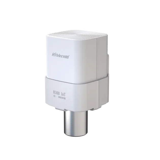
The Hitelecom H Series wireless radar distance sensor measures the distance to a selected surface or target without contact. Monitor water levels and bulk-material heights, or discuss a reference-target arrangement for a defined movement project. Depending on the configuration, readings are sent over 4G, NB-IoT or LoRa to Hitelecom Cloud or a compatible customer platform. Select the range, target, mounting arrangement and reporting profile for your site.
KEY FEATURES
See water, materials and selected positions from a distance. Match the target, installation and data connection to the work your team needs to do.
Measure from above the water or material surface, or along a clear path to a defined target. Plan access and mounting without an immersed sensing probe.
Bring readings from tanks, silos and remote sites into one monitoring view. Set the distance reference and level conversion around the installation.
The published H310-MW012 reference covers 0.3–12 m. Other range and installation requirements can be reviewed as project configurations.
The model reference lists ±1 mm accuracy under 25°C Hitelecom laboratory conditions and 1 mm reading resolution. Select performance around the target and site geometry.
IP68 enclosure protection is listed for the model reference. Match the mounting, exposed sensing face and access for maintenance to the environment.
Choose a 4G, NB-IoT or LoRa configuration around the local network and integration path. Agree sampling, reporting and alert requirements together.
NFC configuration and remote OTA firmware updates are listed in the published product information. Confirm the setup method and update workflow for the supplied configuration.
Associate distance and derived level with a device, vessel or site record. Agree the units, measurement reference, timestamps and payload with your platform team.
MEASUREMENT & INSTALLATION
Start with the value your team needs: a distance, a water or material level, or the change in a target’s position. The mounting reference and measuring path connect the reading to that objective.
Measure the gap along the radar’s viewing direction. Define the target material, size and orientation, and the nearest and farthest positions to observe.
For a fixed sensor above the surface, convert distance into level using the agreed installation reference. Tank dimensions and the material surface guide the mounting point.
Compare distances to the same target along a defined axis. Use an independent stable reference for local movement, or the opposing member for a relative joint gap. Verify the configuration against the change your project needs to resolve.
FROM DISTANCE TO LEVEL
For a vertical, fixed top-mounted installation, level equals the reference height minus the distance to the surface. Define the reference in the same unit and validate it on site.
4.2 m = 6.0 m − 1.8 m
The directly measured gap along the selected measuring path.
A height relative to a defined datum. For the illustrated vertical installation: L = H − D.
Volume uses vessel geometry or a tank table. Flow uses an appropriate structure or site-specific relationship. Agree these calculations with the platform team.
FROM DISTANCE TO TARGET MOVEMENT
For movement observations against an independent reference, compare the distance to the same target at each observation. The reference stays independent of the movement being assessed; the measurement axis defines which component of movement is observed.
Specify the change your engineer needs to resolve, then verify target return, repeatability, temperature effects and reference stability at the site. A vertical settlement interpretation requires a vertical measuring arrangement or separately validated survey geometry.
For joint or bearing-gap observations, the mounting member is the relative reference. Absolute movement requires a separate stable survey reference.
Use a rigid, accessible mounting point and a clear path to the intended surface or target. Check the complete distance span, target size and alignment, nearby structures, fill streams and environmental conditions. For movement projects, establish an independent reference and baseline, then verify repeatability against the required change. Commission the reading and reference together.
FROM A READING TO A RESPONSE
Sampling is when the sensor measures. Reporting is when the reading reaches the platform. Define both around how quickly the level or target can change, then agree the alert and response workflow.
The selected radar configuration reads the distance to the intended target. Choose the sampling schedule and verify the reference against the installation.
The chosen cellular or LoRa configuration carries readings through the agreed network path. Match scheduled reporting and configured alerts to the operational need.
Review distance, derived level and trends in the connected platform. Define thresholds, recipients and the next action for your operations team.
The current H Series datasheet gives a battery-life reference of more than 10 years with scheduled reporting every four hours. The 19,000 mAh battery is the H300 reference configuration. Actual service life depends on the supplied battery, measurement activity, transmissions, network conditions and temperature. Specify faster-changing applications with their required update and response times.
APPLICATIONS
Choose by what the radar actually observes: a visible water or material surface, or a defined target relative to an agreed reference. Explore 48 measurement briefs across drainage, storage, industrial processes and civil infrastructure.
8 industry categories 48 monitoring tasks
AI-assisted product composites show proposed sensor positions and measured surfaces or targets. Illustrative installations; mounting is selected for each project.
The first four categories cover surface-level selection. The following four are reference-target projects requiring engineering review of geometry, site repeatability and the selected model before specification.
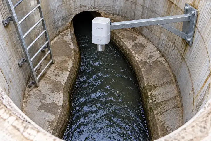
Observe water levels and exposed sediment surfaces at defined drainage points. A documented datum or clean-pit baseline gives each reading meaning, while chamber geometry, surface condition and maintenance timing guide the project selection. Compare the trends with rainfall and inspection records to plan the next visit.
Measure the distance to the water surface in a selected sewer manhole and relate it to the chamber’s surveyed level reference. The resulting trend helps drainage teams review surcharge, rainfall response and how quickly the level returns after an event. Choose a fixed upper mounting position with a clear view past ladders and pipework, then assess condensation, foam and the expected high-water condition. An unusual level provides a reason for targeted inspection; identifying the cause and position of a pipe blockage requires the wider drainage investigation.
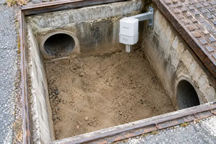
Measure the distance to an exposed sediment surface when a catchpit is dry or drawn down sufficiently to reveal the deposit. A fixed mounting height and a recorded clean-pit baseline allow the local deposit height to be compared over time. This can help maintenance teams prioritise inspection and cleaning at the observed point. Select a broad, representative patch away from inlet jets and assess the return signal as the surface changes. During standing-water periods, interpret the observed surface accordingly; submerged sediment thickness is a separate measurement task.
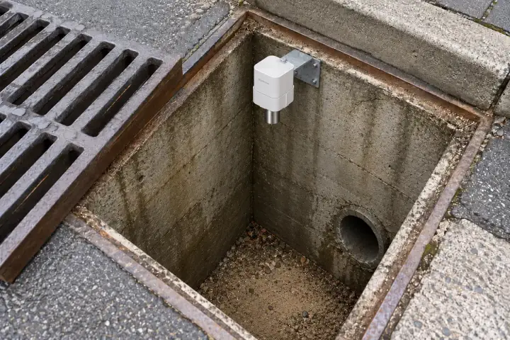
Observe the exposed sand or silt bed inside a roadside gully during suitable low-water or dry periods. Relate the distance to a fixed chamber reference and the surveyed clean floor to follow local accumulation between maintenance visits. The trend can support cleaning priorities when combined with the gully’s rainfall response and inspection records. Keep the measuring path clear of the grate and surrounding metalwork, and select a model whose minimum distance fits the chamber. Document whether each observation represents exposed deposits or a covering water surface.
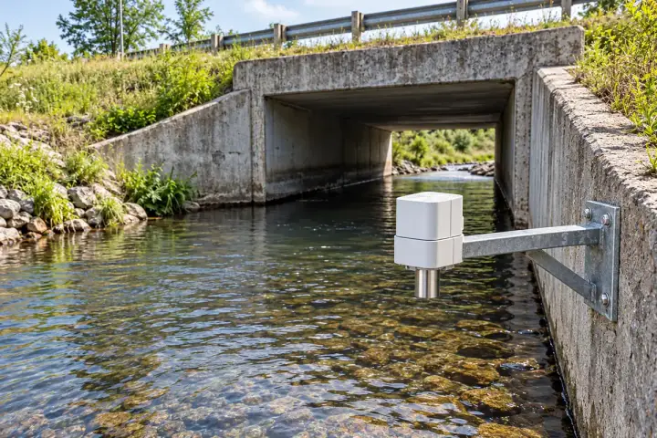
Measure the upstream water surface at a fixed point beside a culvert inlet. A surveyed headwall or bank-mounted bracket connects each distance reading to the site’s water-level datum. The trend helps the drainage team compare rainfall response, drawdown and conditions before an inspection or cleaning visit. Place the observation area away from inlet turbulence, floating debris and passing traffic, with sufficient clearance across the full stage range. Compare upstream readings with downstream levels and site observations to understand a change in drainage performance and plan the next investigation.
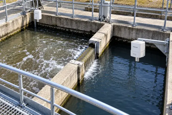
Use separate radar observations at approved upstream and downstream points to follow the water-level relationship across a selected drainage reach. Survey both mounting references to a common datum and compare time-aligned readings with rainfall, pumping and inspection records. A changing difference can help the operator decide where to investigate drainage performance or arrange maintenance. Select representative surfaces at both points, check local turbulence and record the conditions around each observation. The interpretation belongs to the site’s hydraulic and maintenance assessment, supported by the paired measurements and wider operating context.
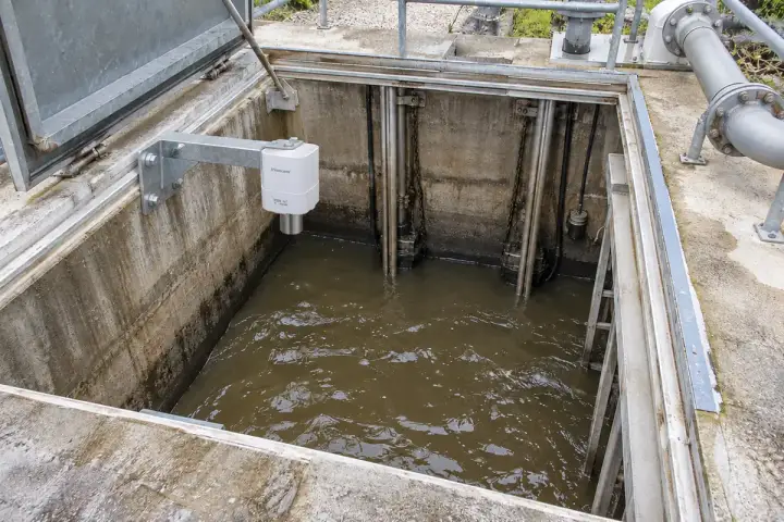
Measure the wastewater surface inside a lift-station wet well from an approved upper mounting position. Reference the distance to the chamber survey so operators can review filling and drawdown alongside pump run records. These observations can support service planning, operating-profile review and comparison between stations. Locate the surface patch away from inflow spray, ladders and pump risers, then assess foam, vapour exposure and the highest expected level. Specify the observation and reporting intervals for the actual cycle, and confirm the site classification and appropriate equipment configuration before installation.
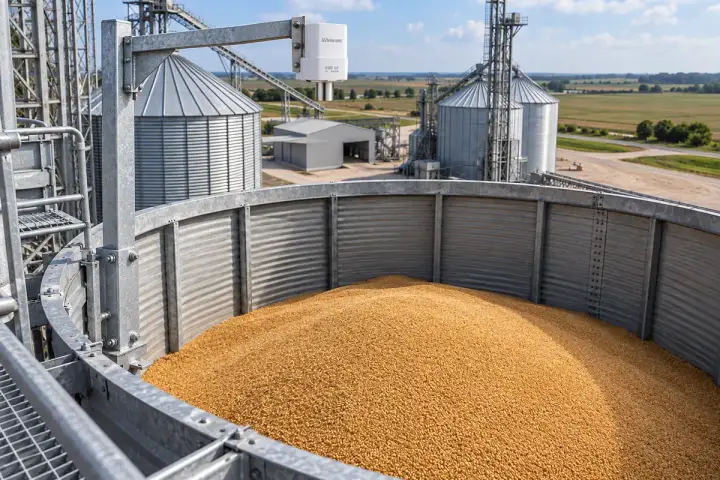
Follow local fill height in grain stores, feed hoppers and biomass bunkers. Each observation is referenced to the vessel or floor, with the material, changing surface and loading activity reviewed for selection. Broader inventory estimates use the project’s geometry and separately agreed calibration.
Measure the distance to the grain surface at a defined point inside a silo. Relate the reading to the fixed roof reference and surveyed empty level to follow local filling and drawdown. The trend helps the storage team plan deliveries, compare operating cycles and check the reserve at the observation point. Choose a clear path away from the filling stream, wall and internal ladders, then validate the return as the grain cone changes. An inventory estimate can be configured separately using the silo geometry, material behaviour and agreed calibration method.
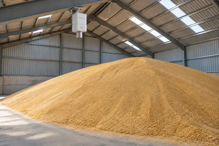
Observe the surface of a grain heap beneath a fixed roof beam or independently supported bracket in a floor store. Survey the reference to the storage floor and track local heap-height changes at the chosen point. This helps the warehouse team compare filling, drawdown and available headroom across designated bays. Position the measurement away from moving loaders, conveyor drops and shifting roof attachments, and assess the echo over the expected heap shapes. Use additional points or a separately validated geometry model when the project needs a wider description of the stored pile.
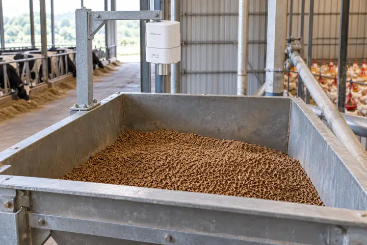
Measure the pellet or granular-feed surface in a hopper from a fixed upper position. A known empty-hopper reference turns the distance into local fill height for replenishment planning and comparison with feed use. Choose a surface patch clear of the supply pipe and auger movement, then review changes during filling and discharge. Hopper shape, bridging and sloped material surfaces influence how a single point represents the reserve. Match the model, installation and approved equipment configuration to the feed material and environment, with reporting timed to the farm’s delivery and service routine.
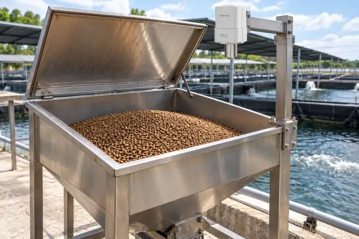
Observe the pellet surface in an aquaculture feed bin or supply hopper at a fixed point above the material. Reference the distance to the empty-bin geometry to follow local drawdown between replenishment visits. The trend helps farm teams compare reserve use across feeding areas and prepare the next delivery. Select a clear view away from transfer equipment and assess the return as the pellet surface changes. Specify the moisture exposure, condensation, feed dust and service access for the installation, while aligning the reporting profile with the farm’s actual feeding and replenishment schedule.
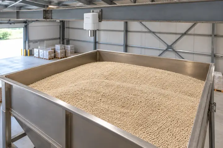
Measure the surface of the specified fertilizer granules inside a supply bin or bounded storage area. Establish a fixed empty-level reference so the distance can be interpreted as local material height and compared with batching or replenishment records. Select a broad patch away from the filling stream and assess the changing slope during discharge. The project review should identify the exact formulation, corrosion exposure, dust characteristics and any classified-location requirements. Where quantity estimates are needed, agree the vessel geometry and calibration separately from the surface-height observation used by the operations team.
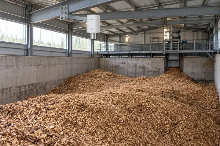
Measure the woodchip or biomass surface at a selected point beneath a fixed bunker reference. Relate the distance to the surveyed floor so the team can follow local reserve height during loading and withdrawal. The observation supports replenishment planning when reviewed with conveyor activity and consumption records. Choose an area clear of loaders and filling streams, and evaluate the return across uneven, changing material surfaces. Confirm the material, dust classification and equipment configuration for the site. Wider inventory calculations require the bunker geometry and a method that accounts for the pile’s changing profile.
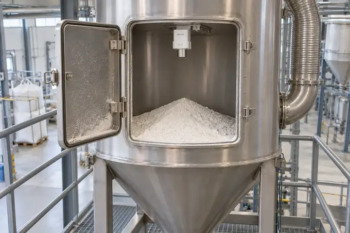
Observe selected powder, pellet, coal and mineral surfaces from an approved fixed position. Material properties, dust, process exposure and required site approvals guide the configuration. The local height trend supports supply planning, with any wider quantity estimate configured around verified storage geometry.
Measure the exposed surface of the specified chemical powder or additive in a supply bin. A fixed upper reference and documented empty level allow local fill height to be trended alongside batch use and refill records. Position the measuring path away from filling jets, mixers and internal obstructions, and evaluate the echo through the expected surface changes. Selection includes the actual formulation, dust loading, vapour exposure, materials compatibility and any required hazardous-area approvals. The project configuration should match these conditions before the readings are used for routine material planning or a separately calibrated inventory estimate.
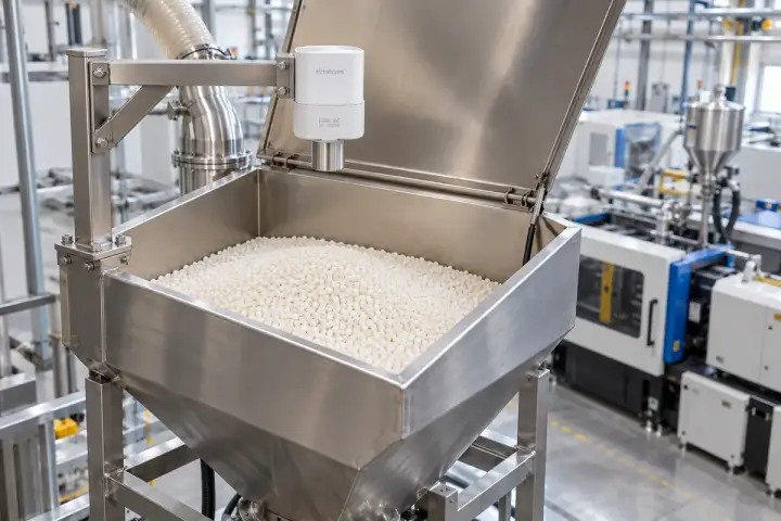
Observe the polymer pellet surface in a hopper supplying a plastics process. Survey the fixed mounting reference to the empty hopper so distance readings can be related to local fill height and reviewed with batch demand. Choose a representative patch away from loading tubes and moving feed equipment, then test the return for the specified polymer and surface slope. The installation review should include temperature, static or dust conditions, nearby structures and service access. A calibrated quantity estimate can be added when the hopper geometry and material behaviour support the project’s inventory requirement.
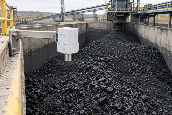
Measure the coal surface at a defined point inside an above-ground bunker. Reference the distance to the bunker’s surveyed empty level and compare local drawdown with handling activity and replenishment records. Select a clear path away from the conveyor drop, wall and steelwork, then evaluate the response across coal sizes, dust conditions and changing pile slopes. Specify the required equipment approvals and installation arrangement for the site before selecting the configuration. The resulting local height trend supports fuel-handling planning; broader inventory estimates need bunker geometry, surface representation and a separately agreed calibration method.
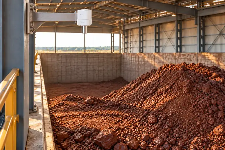
Measure a selected surface area of an ore or mineral stockpile beneath a fixed structural reference. A surveyed floor or empty-bay level connects the distance to local pile height for material-handling and replenishment planning. Position the observation away from loader routes, falling material and nearby steelwork, then verify the return across the expected rock sizes and surface angles. The model and mounting arrangement should match the required range, dust environment and site approvals. Where the project needs total stockpile quantity, combine suitable geometry and additional observations through a separately validated inventory method.
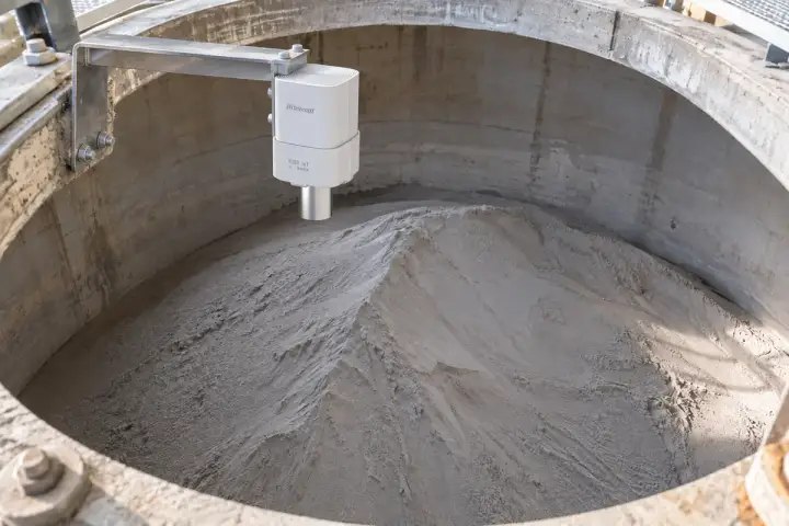
Measure the cement or lime surface through an approved upper silo connection. A fixed reference and documented empty level allow the distance to be expressed as local fill height and compared with material delivery and discharge records. Choose the position around the inlet stream, silo walls and internal structures, with a return-signal trial covering expected powder slopes and filling conditions. Specify dust, material compatibility, process temperature and any required approvals before configuration. The observation supports supply planning at the selected point; stock quantity requires the silo geometry and a separately calibrated interpretation of the material surface.
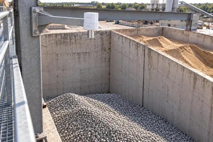
Observe sand or aggregate at a selected location inside a bounded bunker or storage bay. Relate the measured surface distance to the fixed overhead reference and surveyed bay floor to follow local height changes through loading and removal. The trend helps the materials team compare consumption and plan the next replenishment. Position the observation away from loader travel and filling drops, and assess the return over changing particle sizes and pile slopes. Confirm the installation environment and required configuration, while treating any whole-pile volume estimate as a separate geometry and calibration task.
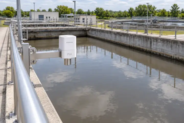
Connect waterworks, reservoir and process-tank surface observations to a surveyed datum. The installation is selected around liquid conditions, fixed mounting, access and the required operating range. Review the level trend with site records, using verified geometry for any separately configured storage estimate.
Measure the water surface in a selected waterworks process basin from a fixed position above the liquid. Survey the reference to the basin datum so distance readings can be compared as water level across filling, transfer and drawdown periods. This gives operators a local storage trend to review alongside pump and treatment records. Choose a surface patch away from aeration, spray, floating debris and internal equipment, then check the reading across the intended operating range. Match the reporting profile and approved installation materials to the waterworks process, maintenance access and actual operating conditions.
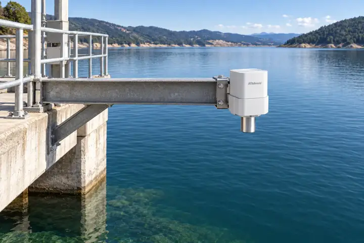
Measure the water surface beneath a fixed reservoir-side pier or short cantilever. Relate the distance to the station’s surveyed datum to build a local water-level record for resource planning, seasonal review and comparison with other observations. Select a clear surface patch outside boating activity, overhanging vegetation and strong inflow turbulence, and assess the expected waves and full stage range. Check the stability of the mounting reference over time. Reservoir storage estimates can be configured separately using an accepted level-to-volume relationship and the site’s surveyed geometry.
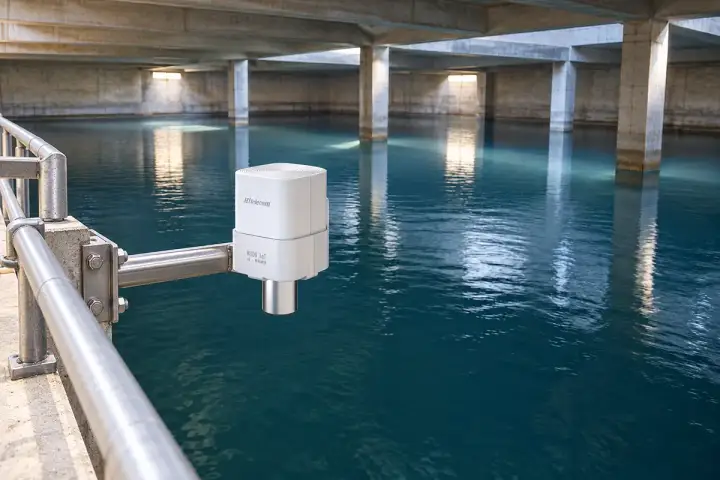
Measure the water surface inside a covered drinking-water reservoir through an approved roof opening or internal service position. Tie the fixed mounting height to the reservoir survey so operators can follow local level during replenishment and demand changes. These observations can support reserve review and planned service visits when combined with the waterworks’ operating records. Select a clear view away from beams, ladders and inlet spray, and confirm condensation, access and the full operating range. Use the site’s approved materials and hygiene procedures, with any storage-volume conversion based on verified reservoir dimensions.
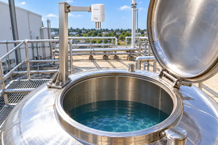
Measure the water surface inside a building storage tank through an approved upper connection. Reference the distance to the tank’s known empty and full levels so the facilities team can compare drawdown, refill events and available reserve. Position the observation away from float assemblies, filling spray and internal pipework, with clearance maintained throughout the operating range. Confirm the opening, condensation and materials requirements for the actual tank. Match reporting to the building’s consumption and service schedule, and use verified tank dimensions when a separately configured volume estimate is required.
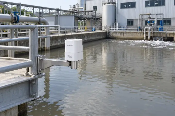
Measure the wastewater surface in a textile or dyeing equalization basin from a fixed upper position. Survey the mounting reference to the basin datum so operators can compare fill, drawdown and transfer events alongside treatment and pumping records. The trend helps coordinate the buffer serving the next process stage. Choose a representative surface away from strong mixing, inlet spray and floating material, then assess foam and chemical vapour exposure. Specify materials compatibility, installation approval and reporting for the actual wastewater process, with any volume estimate based on the basin’s verified geometry.
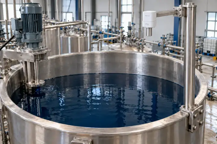
Observe the exposed liquid surface in an approved dye-bath preparation or process-supply tank. A fixed mounting reference and recorded empty level allow the distance to be interpreted as local fill height through batch preparation and withdrawal. The production team can review this trend with recipe preparation, replenishment and service records. Locate the measurement away from mixer blades, pipework and inlet spray, then evaluate the return across agitation and surface changes. Confirm the actual chemistry, vapour, temperature, equipment approval and service access before selecting the configuration and any separately calibrated quantity conversion.
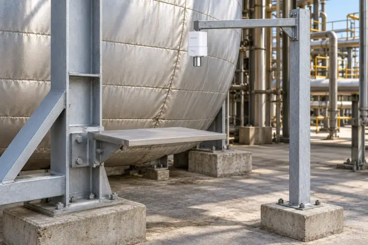
Develop a project around one physically coupled equipment or vessel target and a defined reference. Confirm the observation axis, reference behaviour, target return and installed repeatability before selecting the configuration. Agreed operating states and timing make the resulting distance trend useful to the engineering team.
Observe distance change to a broad approved target on a cool, accessible external boiler support. The reference mount is established independently of that support and checked against the project’s stable benchmark. In the illustrated vertical arrangement, baseline comparisons can describe the target’s movement along the observation axis through agreed warm and cool operating states. The engineering review defines which operating conditions are comparable and evaluates mounting temperature, repeatability and required observation timing. Keep the installation outside hot process exposure and select the configuration from the verified target return and the project’s measurement requirement.
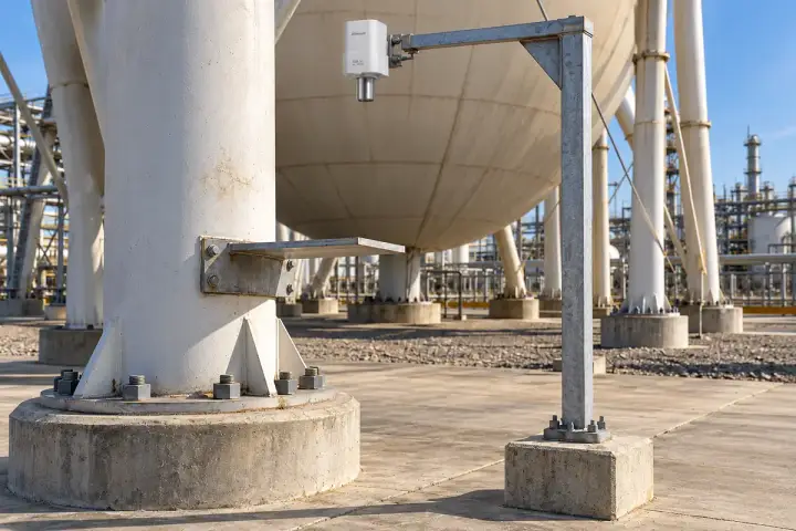
Measure the distance to a broad approved target attached to a selected spherical-tank support. Establish the neighbouring reference on a separately surveyed foundation and confirm its stability for the observation period. A documented baseline and validated vertical layout allow the engineering team to compare local support movement through defined operating conditions. Target attachment, clearance, return-signal behaviour and temperature effects are assessed as part of the project configuration. The interpretation applies to that selected target and axis, with the tank owner defining access, classified-location requirements and how the reading fits the wider vessel-monitoring plan.
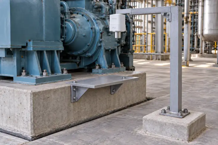
Observe a broad target attached to the accessible edge of a machine foundation. The nearby reference is tied to an independently verified benchmark so its stability can be checked separately from the foundation being monitored. Compare the distance with the accepted baseline during agreed machine states and service periods. For a vertical arrangement, establish the axis geometry before interpreting local vertical movement. The project trial assesses target return, mounting temperature and repeatability under the expected operating conditions, while the engineering team determines how this selected-point observation contributes to its foundation inspection and maintenance programme.
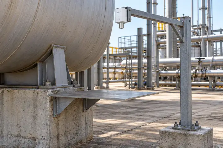
Measure an approved target on a selected storage-tank support from a separately referenced fixed mounting point. Document the initial distance, target attachment and observation axis, then compare readings across agreed service states. In a vertical layout, verify the reference stability and axis before reporting a local support-height change. The configuration review considers target return, expected movement, nearby pipework, temperature and access throughout the tank’s operating cycle. The resulting observation supports engineering review of the selected support, with the wider tank survey and inspection records providing the context for interpretation and maintenance decisions.
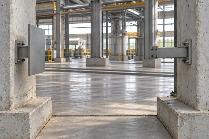
Measure the distance across a factory structural joint to a broad approved target fixed to the opposing member. Document both attachment points and the observation axis so baseline comparisons describe the relative opening at the selected location. The engineering team can review this trend with temperature, construction activity and service records. Validate the target return and clear gap over the expected movement range, and establish the required field repeatability before selecting the configuration. Interpret the reading as the relationship between those two members, with independent survey references used where the project also requires absolute movement information.
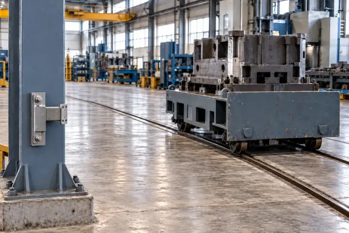
Observe a broad target on slow-moving equipment or a carriage from a fixed reference at the end of the measuring path. Relate the distance to a documented baseline to compare positions at stable stops or during an agreed slow observation profile. This can support operating records, inspection planning and position checks in a defined installation. Keep the path clear of other equipment and verify the target return across the full travel. The project specifies the required timing, movement speed, field repeatability and platform handling before selecting a configuration for the observation task.
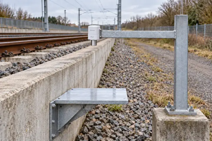
Rail, tunnel and port observations start with approved targets, clear measuring paths and verified reference layouts. Each project confirms attachment, geometry, installed repeatability and observation timing before configuration. Interpret the selected-axis records alongside the infrastructure owner’s survey and inspection programme.
Measure a broad approved target attached to the outside edge of a railway track-support slab. Establish the reference on a separately surveyed foundation outside the assessed movement zone and vehicle envelope. A validated vertical observation axis allows baseline comparisons to support review of local support-height change during agreed static or maintenance windows. Target return, nearby metalwork, reference stability and the required repeatability are evaluated before configuration. The railway engineer defines the target attachment and access arrangement, together with the observation schedule and how these selected-point records fit the wider track survey and maintenance programme.
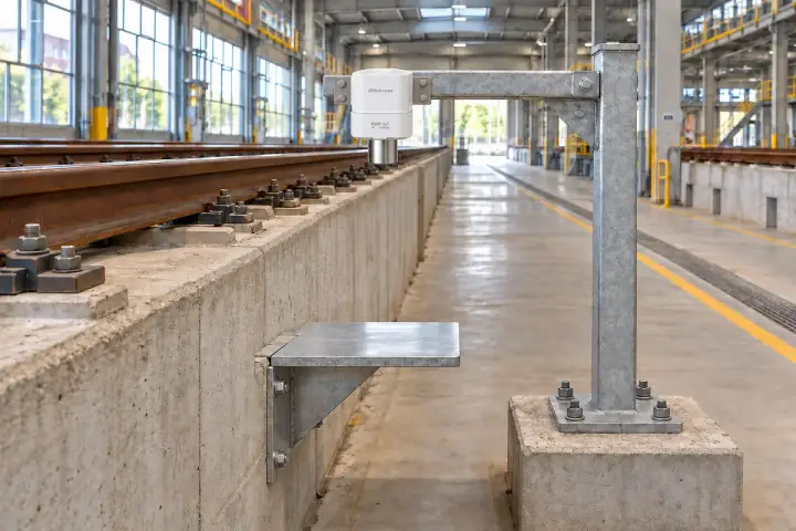
Observe a broad target attached to a selected light-rail support or plinth from an independently established nearby reference. Document the initial distance and verify the vertical measuring axis before interpreting local height change. Take comparable observations during agreed static or service conditions and review them with the rail engineer’s inspection and survey records. The project assessment confirms target attachment, clearances, return-signal behaviour and reference stability across the required period. Configuration then follows the smallest change that must be resolved, the acceptable field repeatability and the observation timing agreed for the specific support location.
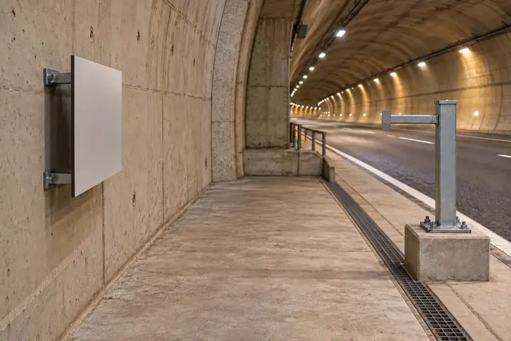
Measure a broad approved target on a selected highway-tunnel lining segment from a surveyed fixed reference in a protected service area. Record the baseline distance and measuring direction so the tunnel engineer can interpret change along that axis. Review observations with construction activity, temperature and the wider monitoring survey. The project confirms the reference’s stability, target attachment and return signal through the expected conditions, with clear separation from traffic and other moving objects. The selected configuration and reporting profile follow the required change, field repeatability and monitoring period defined in the tunnel’s engineering plan.
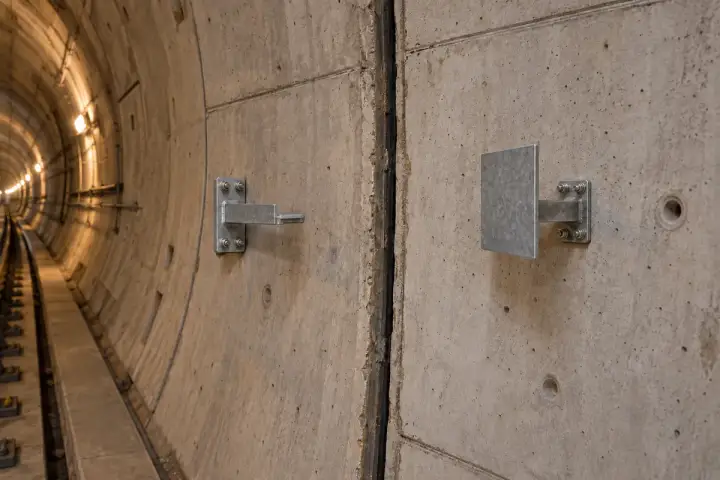
Observe the distance from an offset bracket on one tunnel segment to a broad approved target attached to the adjacent segment. Establish a clear measuring baseline within the selected model’s range, rather than using the narrow physical joint as the sensor-to-target gap. Document both attachments, the joint geometry and the initial reading to follow relative opening along the selected axis. The records can support engineering review alongside temperature, construction and tunnel survey observations. Evaluate clearance and target return over the expected joint movement, and define the installed repeatability required for meaningful comparisons. Where the project also needs absolute segment movement, reference each segment to the wider surveyed monitoring network established by the tunnel engineer.
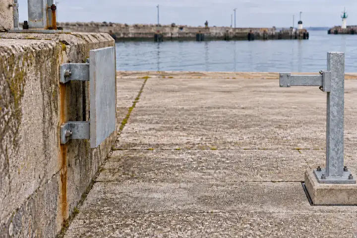
Measure a dry, exposed target attached to the selected quay-wall element from a separately surveyed land-side reference. Establish the initial distance and measurement axis, then assess reference stability and target return through the intended observation period. The port engineer can review local distance change with tide, temperature, loading and inspection records. Choose a protected service position with a clear short path and confirm that vessels, vehicles and temporary works stay outside the observation area. Configuration and reporting are selected against the required field repeatability and the movement the engineering plan intends to observe.
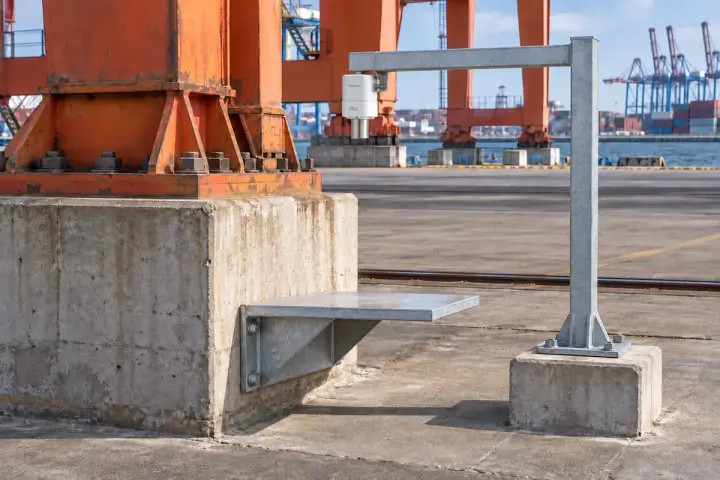
Observe a broad target attached to an accessible port-equipment foundation from a nearby independently surveyed reference. In the vertical arrangement, verify the reference stability and axis before relating baseline distance changes to local foundation-height change. Compare observations during agreed equipment states and review them with load, temperature and inspection records. The project assessment confirms target attachment, the return signal, clear space and reference behaviour through the monitoring period. Select the configuration and timing from the engineer’s required repeatability, smallest relevant movement and approved service access around the gantry or other port equipment.
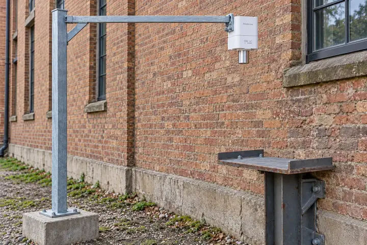
Create a project for a selected building, bridge or heritage point using an approved surface or physically attached target. Verify the reference and observation direction, with vertical geometry established for local settlement interpretation. Field acceptance and authorised mounting guide configuration and the role of each record in the wider assessment.
Measure a broad approved target securely attached to the selected lower building element through an authorised mounting arrangement. Establish the independent reference outside the assessed movement zone, verify its stability and document a vertical measuring axis. Baseline distance changes can then be reviewed as local vertical movement within the engineer’s accepted monitoring layout. The project trial establishes installed repeatability across temperature and service conditions, with survey checks confirming that the reference remains stable. These selected-point records support the building assessment alongside inspection and wider survey evidence, using the observation interval agreed for the actual site.
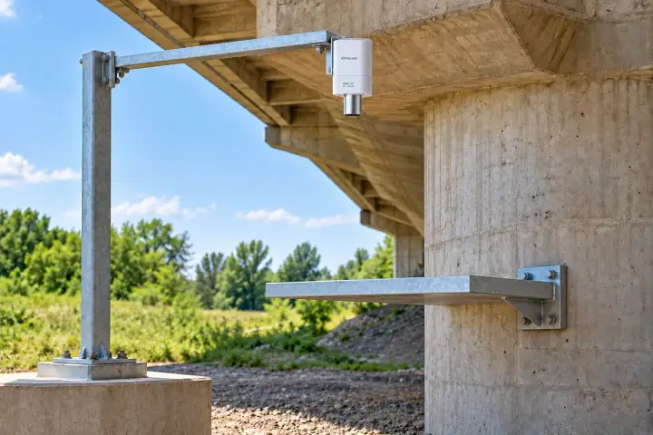
Observe a broad target attached to an accessible bridge-pier element from a separately surveyed reference. Establish a clear vertical measuring axis and accepted baseline before comparing local vertical movement over the monitoring period. The bridge engineer defines target attachment, reference checks and comparable load or temperature conditions for interpreting each observation. Verify the return signal and installed repeatability for the smallest change required by the project. A protected short path and documented datum connect these selected-point records to the wider bridge survey, with timing chosen for the intended long-term or service-period observation.
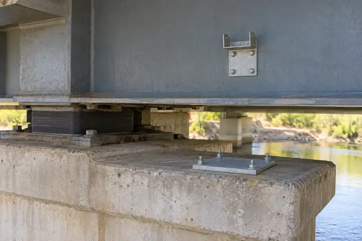
Measure the distance from an approved bracket on the bridge beam to a broad horizontal target fixed to the pier cap beside the bearing. The downward-facing sensor and offset target provide a clear observation path outside the bearing mechanism. Document the baseline and vertical axis to compare the relative relationship between beam and support under agreed load and temperature conditions. Validate target return, clearance and installed repeatability across the expected movement, and review the trend alongside bearing inspections and survey records. Independent survey control provides the wider context when the project also needs absolute beam or pier movement.
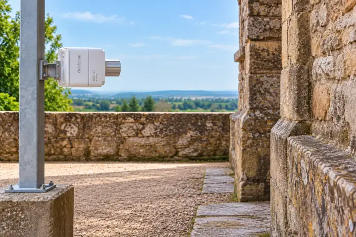
Measure an existing broad wall surface along a conservation-approved direction from an independently established nearby reference. Where an attached target is needed, its installation follows the conservation authority’s approved method and remains physically coupled to the wall being observed. Document the surface, reference, axis and baseline, then evaluate return stability and installed repeatability across the planned period. Distance changes support review of that selected wall point alongside the conservation survey and inspection record. Preserve access and the clear measuring path, with reference checks and observation timing agreed by the project’s conservation and engineering team.
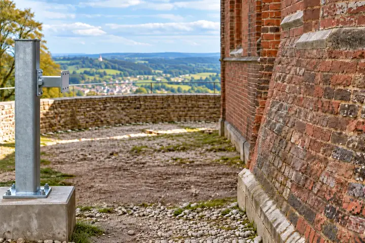
Observe a broad accessible tower face, or an approved target attached to the selected tower element, from an independently surveyed reference. Establish the observation direction and baseline so the conservation engineer can interpret changes along that axis. Test the return on the actual masonry or attached target, and confirm reference stability and installed repeatability through the expected weather and temperature conditions. The project chooses a protected short path and an authorised mounting arrangement that respects the historic fabric. Review these local observations with the wider tower survey and inspection programme over the agreed monitoring period.
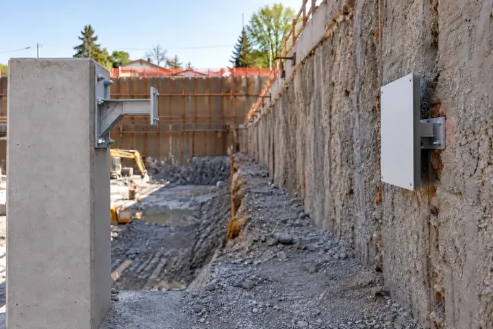
Measure a broad approved target attached to the selected construction retaining-wall segment. Establish the reference on a surveyed foundation outside the assessed excavation movement zone and document the initial distance and observation axis. The construction engineer can compare local distance changes with excavation stages, ground conditions and survey records. Assess target return, reference stability and field repeatability before choosing the configuration and reporting profile. Protect the measuring path from equipment, stockpiles and temporary works, with reference checks and access arranged for the full construction period covered by the approved site monitoring plan.
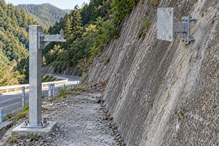
Design a project around an approved target coupled to the selected slope, dam or embankment point. Verify the reference, axis and installed repeatability before choosing configuration and timing. Review the local records with the geotechnical or dam survey, using explicit relative geometry for joint observations.
Measure a broad target securely coupled to an approved point on an engineered slope. Establish the reference on a surveyed stable foundation outside the assessed moving section, with a clear short path aligned to the project’s observation direction. Compare distance changes with the baseline and review them alongside rainfall, site activity and geotechnical observations. The engineering trial confirms target coupling, return stability and the repeatability needed for the intended change. Select the configuration and reporting profile for that point and axis, while the wider monitoring plan provides the context for the slope assessment.
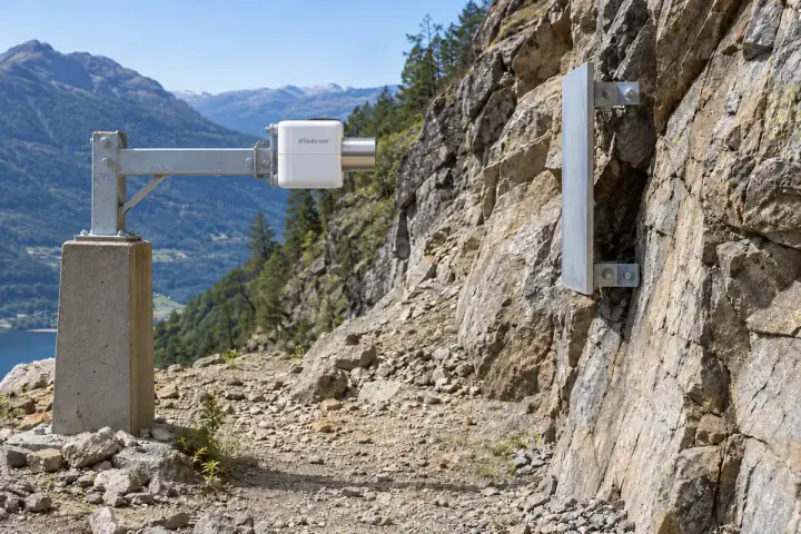
Observe a broad approved target anchored to a selected sound-rock point from an independently established reference outside the assessed movement area. Document the baseline, target coupling and observation axis to compare local distance changes through the agreed monitoring period. The geotechnical engineer defines the point’s role and reviews its records with rainfall, inspection and the wider monitoring survey. Test the return signal and installed repeatability over expected weather conditions, keeping vegetation and site equipment clear of the path. Configuration follows the required range, relevant movement and reporting interval for this selected-point project.
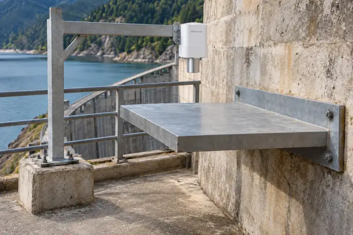
Measure a broad target attached to an accessible concrete dam-abutment element from a separately surveyed reference. Establish the initial vertical distance and verify reference stability before interpreting changes at the selected point. The dam engineer can review these observations with reservoir stage, temperature, inspection and survey records under the accepted monitoring plan. A project trial checks target return and installed repeatability across the expected conditions. Keep the measuring path protected and document target attachment, axis geometry and reference checks, with the configuration and observation interval selected for the movement and monitoring period the project requires.
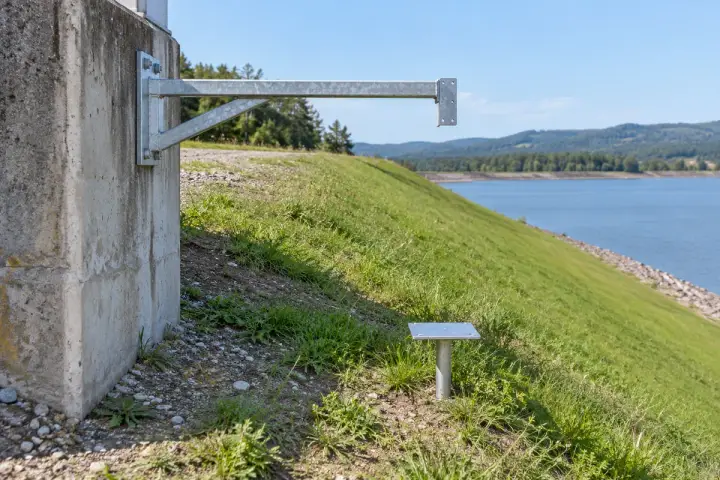
Measure a broad target attached to a defined survey point within the embankment monitoring zone. Establish the observation reference independently outside the assessed movement area and verify the vertical geometry before comparing local height changes with the accepted baseline. Review the target records with the geotechnical survey, rainfall and site activity over the agreed period. The engineer confirms how the selected survey point is coupled to the ground being observed, together with reference stability and installed repeatability. Configuration and reporting follow that specific point’s required movement sensitivity, access conditions and field acceptance criteria.
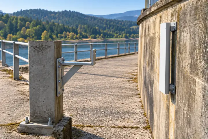
Observe a broad approved target attached to a selected reservoir retaining-wall segment from an independently surveyed land-side reference. Document the baseline distance and observation direction so local changes can be reviewed within the wall’s engineering monitoring plan. Compare the records with reservoir level, weather, loading and inspections as appropriate to the site. Verify reference stability, target return and required installed repeatability before selecting the configuration. Keep the short measuring path clear of vegetation, vehicles and temporary works, with accessible reference checks maintained throughout the intended observation period for the selected wall point.
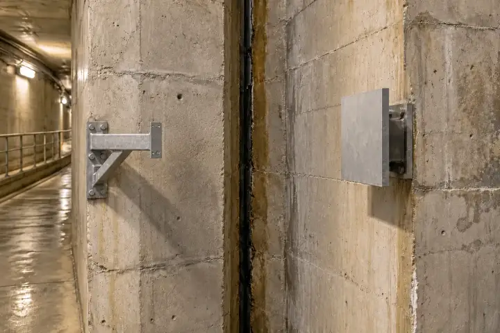
Measure a broad approved target attached to one dam-gallery segment from a mounting point on the opposing segment. Record both attachments, the initial gap and the observation axis so readings describe relative joint opening at that location. Review changes with reservoir stage, temperature, inspections and the dam’s monitoring records. A project trial verifies target return, clearance and installed repeatability over the expected movement and gallery conditions. The configuration is selected for this defined inter-segment observation, with independently surveyed references included where the engineering assessment also requires absolute movement of either segment.
SERIES & CONFIGURATIONS
H Series product form, measurement range and wireless connection are selected for the project. H200, H300 and H500 are published family identifiers; H310-MW012 provides the model-specific reference below. Share your measuring path before choosing a final configuration.
Select the regional cellular configuration and SIM service. Review signal conditions at the mounting point, the reporting profile and the platform connection.
Discuss 4G ↗Review NB-IoT service, bands and operator support in the installation country. Match the network and update requirements to the supplied terminal.
Discuss NB-IoT ↗Plan the selected LoRa receiver or gateway, site coverage and platform path. Confirm the radio protocol and payload for the project.
Discuss LoRa ↗| Reference model | H310-MW012 |
|---|---|
| Measuring range | 0.3–12 m |
| Published accuracy | ±1 mm · 25°C Hitelecom laboratory conditions |
| Reading resolution | 1 mm |
| Beam angle | <20° · published model reference |
| Enclosure protection | IP68 |
| Battery capacity | 19,000 mAh · published configuration |
| Battery-life design reference | More than 10 years with scheduled reporting every four hours; service life depends on configuration and operating conditions |
| Operating temperature | −30°C to +75°C |
| Storage temperature | −40°C to +85°C |
| Operating humidity | 5–95% RH · non-condensing |
| Family wireless options | 4G / NB-IoT / LoRa · selected by configuration |
| Local configuration / updates | NFC / remote OTA · confirm the supplied configuration |
| Cellular platform protocol | MQTT · endpoint, authentication and payload agreed for integration |
| Mounting | Mounting lugs, pole clamp or slotted mount · selected for the installation |
APPLICATION-LED CUSTOMIZATION
Start with the surface or target. Review range, measuring path, device form and mounting together, then match power, connectivity and platform integration.
Required nearest and farthest distances, target material and the surface change to observe.
Enclosure form, mounting arrangement, sight line and access suited to the project.
Sampling schedule, reporting needs, operating conditions and maintenance target.
Product identity, platform payload and project documentation agreed with your team.
Surface or object, material, orientation, distance span and the change your team needs to observe.
Mounting reference, vessel or site geometry, environmental conditions and practical access.
Sampling, reporting, wireless service, level calculations, platform fields and the alert workflow.
CONNECTIVITY & INTEGRATION
Choose the destination for your distance readings and derived levels. Cellular configurations can use the agreed MQTT connection; LoRa configurations use the selected radio receiver or gateway and platform integration.
Associate each reading with its tank, silo, target or site. Review distance, the agreed level conversion, trends and configured alerts in the connected monitoring view.
Bring radar readings into your own operations view. Agree the cellular MQTT endpoint or selected LoRa integration, authentication, payload and any level or inventory calculation.
Check a sample message against a known target distance. Confirm the reference, units, timestamps and any level calculation, then test the notification path with the team responsible for the site.
Discuss platform integration ↗ANSWERS FOR YOUR PROJECT
Answers on surface levels, manhole maintenance, reference-target projects and the information needed for a suitable configuration.
Ask about your project ↗A radar distance sensor uses reflected radio signals to measure the distance from its measurement reference to a target surface. The Hitelecom H Series sends readings for remote monitoring. With an agreed reference and installation, distance data can support water level, tank level, bulk-material level or changes in target position.
Use the nearest and farthest target positions to define the required range. The published H310-MW012 reference specifies 0.3–12 m, ±1 mm accuracy under 25°C Hitelecom laboratory conditions, and a 1 mm reading resolution. Share the target material and installation geometry so Hitelecom can review the appropriate configuration, including requests for other ranges.
For a fixed sensor mounted vertically above the surface, level is calculated from the configured reference height minus the measured distance to the surface. Volume uses the vessel geometry or a calibrated tank table. For bulk solids, the mounting position and surface profile also matter; a local level reading supports inventory planning when interpreted with the agreed vessel and material information.
Radar is used for liquid surfaces and for bulk materials such as grain, pellets and aggregates. Selection depends on the material, surface conditions, vessel shape and accessible mounting position. Share the medium, filling method and expected environment with Hitelecom to review a suitable configuration for your tank, silo, hopper or open-water site.
A fixed radar above a sewer or drain chamber observes the exposed water surface. Water-level trends, compared with rainfall, pumping and downstream conditions, can help the maintenance team select locations for inspection. Where the chamber is dry or emptied and the deposit surface is exposed, its local height can be assessed against a known chamber datum after confirming the target return.
Specify whether you need water level, exposed deposit height or a submerged sludge interface. The submerged interface is a separate measurement task requiring an appropriate instrument; water-surface distance alone does not identify the amount or location of a pipe blockage.
A defined target can be observed from an independent, stable reference. The difference between the current gap and its baseline is a relative change along the measuring axis. For a settlement interpretation, establish a vertical measuring arrangement or validated survey geometry, with periodic checks of the reference.
Specify the required observable change and monitoring interval, then review target size, alignment, environmental effects and on-site repeatability with the project engineer. These are proposed selection briefs: the published H310-MW012 laboratory distance accuracy is a model reference, rather than a validated field settlement performance specification.
For a joint or bearing gap, the mounting member and opposing target define a relative opening. Independent survey information is needed when the project also requires absolute movement.
Radar uses electromagnetic waves; ultrasonic measurement uses sound waves. Air temperature changes the speed of sound used in ultrasonic measurement; radar does not depend on sound speed. Their response to changing air conditions, dust, vapour and surface conditions differs. Both need an appropriate measuring path and installation. Choose by the medium, required range, available mounting space and site conditions; for foam, condensation or deposits, include those details in the application review.
Use a rigid mounting point with a clear measuring path to the intended surface or target. For level monitoring, plan the mounting position around the vessel shape, fill stream and internal structures, and keep the full operating range within the selected configuration. Establish the measurement reference and verify readings at representative levels during commissioning.
The H Series offers H200 with LoRa, H300 with 4G LTE and H500 with NB-IoT, selected by configuration. Match the network to site coverage and the destination platform, then define sampling, scheduled reporting and alert requirements. The current H Series datasheet gives a battery-life reference of more than 10 years with scheduled reporting every four hours; the 19,000 mAh battery is the H300 reference configuration. Actual service life depends on the supplied battery, measurement activity, transmissions, network conditions and temperature.
Send the application, target material, minimum and maximum measuring distances, mounting position and approximate quantity. A site photo or vessel drawing helps define the measuring path. Include ambient and process conditions, the required reading and reporting intervals, wireless coverage, platform requirements and the level or distance events you want to monitor.
LET'S TALK ABOUT YOUR PROJECT
Tell us what you need to measure and where. We’ll help match the target, range, mounting, wireless connection and platform to your project.
sales@hitelecom.cn ↗Show the vessel or target, available mounting position and nearest and farthest distances. Include your update requirements and destination platform.