


Explosion-protected custom gas sensors.
Your gas.
Your installation.

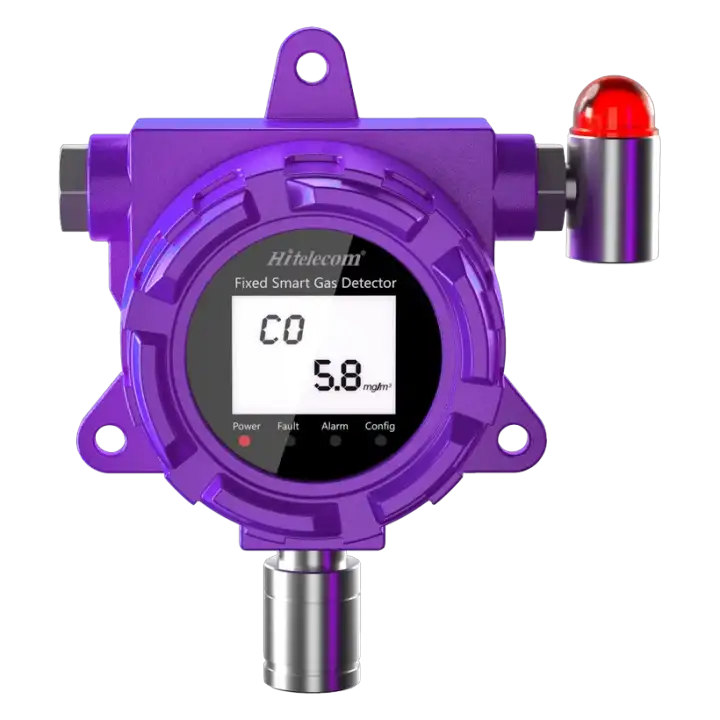
Official Hitelecom H Series fixed gas sensor example showing a CO configuration; target gas and model are selected for the project
Fixed gas configuration example · Gas and model selected for your project

The Hitelecom H Series custom gas sensor measures gas concentration at selected industrial monitoring points. Target gases include CH4, H2, NH3, O2, SF6, CO2, H2S, CO, SO2 and more. Sensing technology, range and units are matched to each target gas and monitoring task. Powered by an external 9–24 V DC supply, the terminal supports fixed or ducted installation and model-dependent wireless reporting. Select the gas channels, site protection, local warning requirements and platform integration as one project configuration.

Gas-specificSelected gas, sensing principle and rangeDefine the channels required for your site
9–24V DCExternal power supplyPlan the supply at the mounting position
Hitelecom platformReadings and configured alertsHitelecom Cloud or compatible integration

KEY FEATURES

Choose the gas.
Connect the next decision.

Bring the target gases, measuring range, site protection requirements and data destination into one monitoring plan.

Gas-specific channels

Select the target gases and monitoring duty: combustible leaks, toxic concentrations or oxygen conditions.

Matched sensing technology

Choose the sensing principle for the actual gas, concentration range, response and process conditions.

Fixed or ducted

Configure point or ducted monitoring around the gas source and intended sampling location.

Wireless data options

Select 4G LTE, NB-IoT or LoRa around regional support, site coverage and the receiving platform.

Configured threshold alerts

Set the concentration thresholds, recipients and monitoring workflow for the selected measurement channels.

External 9–24V DC

Connect the terminal to the specified external supply, with wiring arranged for the installation.

OEM / ODM flexibility

Match gas channels, enclosure, mounting, data and alarm-interface requirements to your project.

Site-matched protection

Select the detector approval, enclosure and gas inlet around the site classification and environment.

CUSTOMIZE BY TARGET GAS

Common gas examples.
More gases, configured for your project.

Start with these common industrial gas examples, or share an additional target gas for customization. Select the gas actually used or released at your site, then match its measurement purpose, sensing technology, range and terminal arrangement to the project.

CH4
Combustible gas

Methane

Typical reporting unit%LEL, ppm or vol%, by duty

Distinguish flammable-gas warning from low-level leak investigation or process measurement; select the methane-capable channel.

Select for my project
H2
Combustible gas

Hydrogen

Typical reporting unit%LEL or ppm, by duty

Select a hydrogen-capable channel for the required concentration range and response. Review any oxygen dependence with the chosen sensing principle.

Select for my project
NH3
Toxic gas / potential flammability

Ammonia

Typical reporting unitppm for toxic monitoring

Specify the toxic leak duty and refrigeration or process conditions; assess additional flammability requirements where relevant.

Select for my project
O2
Deficiency / enrichment

Oxygen

Typical reporting unitvol%

Select an oxygen-specific channel and assess low and high alarm duties. Enriched oxygen supports combustion.

Select for my project
SF6
Nonflammable / displacement risk

Sulfur hexafluoride

Typical reporting unitppm or vol%, by duty

Specify ambient gas concentration separately from sealed-equipment density; assess O2 deficiency as a separate monitoring duty.

Select for my project
CO2
Nonflammable / elevated-concentration risk

Carbon dioxide

Typical reporting unitppm or vol%, by duty

Select direct CO2 measurement for industrial releases; oxygen measurement does not quantify the CO2 concentration.

Select for my project
H2S
Toxic gas / flammable

Hydrogen sulfide

Typical reporting unitppm for toxic monitoring

Define the H2S range, likely interfering gases and sampling materials. Match the sensing and service plan to the actual process.

Select for my project
CO
Toxic gas / flammable at high concentration

Carbon monoxide

Typical reporting unitppm for toxic monitoring

Define a CO-specific toxic measurement channel for combustion or process leaks; distinguish it from a combustible-gas duty.

Select for my project
SO2
Nonflammable / toxic irritant

Sulfur dioxide

Typical reporting unitppm for toxic monitoring

Select the SO2 channel for the expected process release, with humidity, corrosion and interfering gases included in review.

Select for my project
Discuss another target gas

The gases shown are examples, with further target gases available for project-specific customization. Each project defines the supplied gas channels, sensing principles, measuring ranges and units.

DEFINE THE GAS-MONITORING DUTY

Choose the gas.
Define the decision.

Useful gas measurements start with the hazard and the action required at each point. Specify the gas inventory, expected concentrations and site conditions, then select the sensing principle, units, range and installation with the required alarm and response behavior.

01

Gas, units & sensing

Match the measurement to combustible, toxic, oxygen or asphyxiation-related duties. Conventional hydrocarbon infrared sensing does not detect H2; O2 needs an oxygen-specific channel. Confirm the selected principle, range, response and interfering gases.

Define your measurement
Target gas · ppm / vol% / %LEL · Expected concentrations · Response requirement
Discuss this measurement ↗
02

Process & site conditions

Share release sources, gas mixtures, temperature, humidity, airflow and corrosive conditions. Define the hazardous-area classification and applicable market approval, then confirm the supplied detector, enclosure and conditions of use.

Define your measurement
Release sources · Ventilation · Ambient conditions · Area classification · Approvals
Discuss this measurement ↗
03

Installation & data path

Plan monitoring points, external 9–24 V DC power and practical inspection access together. Agree the wireless variant and receiving platform, and specify any required local warning or control interfaces for engineering confirmation.

Define your measurement
Monitoring points · External power · Cable route · Network · Alarm / control needs
Discuss this measurement ↗
SENSING & INSTALLATION

Assess the gas path.
Make every point serviceable.

Choose candidate monitoring points from probable releases, gas dispersion, ventilation, obstructions and occupied locations. Gas density is one input; release temperature, gas mixtures and airflow can change movement. Agree the layout using the selected detector documentation and site assessment. For ducted or sampled monitoring, review the gas inlet, sample materials, condensation, flow and transport time. Plan external power and cable routing with the hazardous-area installation requirements. Keep each point accessible for function testing, calibration and replacement, then commission the complete measurement and alarm path.

FROM GAS MEASUREMENT TO SITE RESPONSE

See the gas condition.
Define the response.

Define sensing, alarm evaluation and data uploading as separate requirements. Specify how quickly the site needs to recognize a gas condition and how the receiving team will act. Confirm response time, upload timing, network-loss behavior and fault reporting with the ordered configuration. Where local warnings or protective actions are required, agree the appropriate local path and verify it during commissioning.

01

Measure

The selected sensing channel measures the target gas at a defined point. Confirm units, range, site conditions and sensing frequency for the duty.

02

Transmit

Readings follow the configured wireless route. Verify coverage, message format, timestamps and delivery to the agreed platform.

03

Respond

Agree thresholds, alarm recipients and site procedures. Confirm any required local warning or control path and its fault behavior as part of the project.

REPORTING & POWERExternal power for the configured duty.

The custom gas configuration uses external 9–24 V DC power. Plan the available supply, wiring, cable route and access for isolation and service with the selected detector. Confirm supply quality, component limits and any project continuity requirements during engineering review. Define the sensing and communication profile for the required monitoring duty, and document the power arrangement together with the installation and applicable hazardous-area conditions.

APPLICATIONS

Industrial gas-monitoring applications.
40 defined monitoring contexts.

Explore eight industrial groups across natural gas, hydrogen, ammonia refrigeration, wastewater and biogas, SF6 electrical equipment, metals and combustion, industrial CO2 and specialty-gas installations. Each context identifies the target gases, monitoring duty, candidate point and project details needed for configuration.

8 application categories 40 monitoring tasks

Illustrative application images. Candidate monitoring points require a site assessment of the gas source, movement, ventilation and selected detector. Gas options are project-specific.
01Natural gas & petrochemical operations5 monitoring tasks
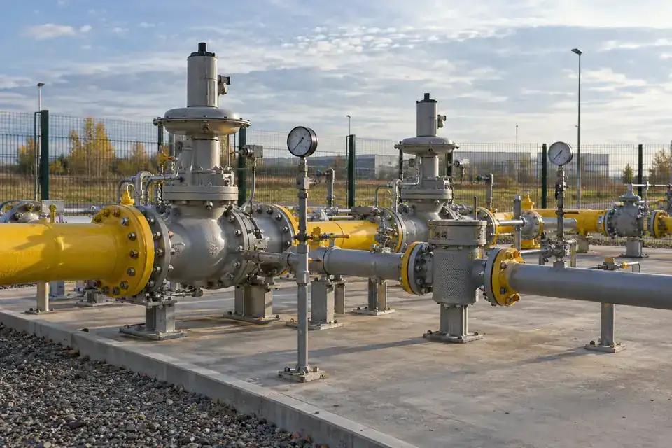
Industrial natural-gas pressure-reduction station with regulators, pipework and accessible valve connections
Natural-gas pressure-reduction stations · Illustrative application image

Select gas monitoring around the actual fuel or process stream and its assessed release locations. Define combustible and toxic channels separately, with a clear range, installation and operating response.

Natural-gas pressure-reduction stations

CH4 concentration at selected ambient monitoring points; ppm or %LEL as specified.
Industrial natural-gas pressure-reduction station with regulators, pipework and accessible valve connections
Natural-gas pressure-reduction stations · Illustrative application image

Monitor methane around the connections and equipment serving a natural-gas pressure-reduction station. An agreed detector layout gives operators a concentration reference alongside inspection and maintenance records. Identify the gas composition, potential release points and site airflow, then specify the measurement range, local warning requirements and remote reporting path for the selected installation.
Measurements to observe
CH4 concentration at selected ambient monitoring points; ppm or %LEL as specified.
Monitoring point
Candidate positions around regulator connections, valve assemblies and the station enclosure, chosen through the gas-detection layout.
Placement & installation
Review release direction, ventilation, weather exposure and access. Match detector approval, gas inlet and cable entries to the classified location and supplied configuration.
Project details
Fuel composition, regulator layout, area classification, measurement objective, alarm setpoints, 9–24V supply and platform.
Discuss this application

Natural-gas compression skids

CH4 concentration around selected compressor service and connection areas.
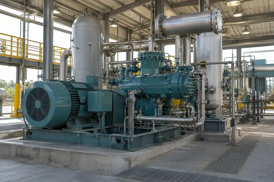
Natural-gas compression skid with recognizable compressor machinery, gas manifolds and industrial service access
Natural-gas compression skids · Illustrative application image

Observe methane concentrations around a natural-gas compressor skid and its accessible service connections. The monitoring task focuses on equipment areas where the project assessment identifies a possible release, rather than a general factory air-quality reading. Define the operating environment, ventilation and desired warning response, then agree detector channels and integration with the station’s existing procedures.
Measurements to observe
CH4 concentration around selected compressor service and connection areas.
Monitoring point
Candidate positions near assessed seal, manifold and valve release points on the compressor installation.
Placement & installation
Consider vibration, airflow, obstructions and service access when selecting the detector location. Confirm the approved mounting, electrical entry and gas inlet arrangement for the site.
Project details
Compressor type, gas composition, possible release points, ventilation, classified area, required units, local indication and receiving platform.
Discuss this application

Boiler-house fuel-gas supply areas

Ambient CH4 for fuel-gas leakage; ambient CO for assessed combustion-gas release paths.
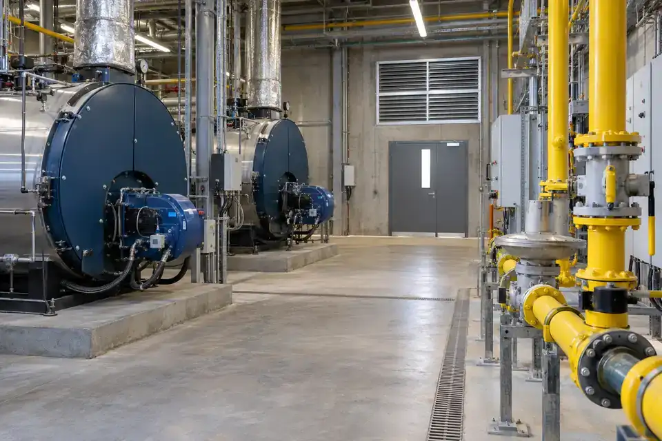
Industrial boiler-house fuel-gas train and service pipework, with boiler equipment visible in the background
Boiler-house fuel-gas supply areas · Illustrative application image

Monitor the fuel-gas supply area serving an industrial boiler house. Methane monitoring can address the assessed fuel-release task, while a separate CO channel may be specified for the combustion-related monitoring objective. Treat these as defined measurement points with their own ranges and locations, and coordinate their alarm and response requirements with the boiler-house operating team.
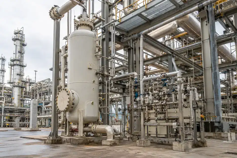
Measurements to observe
Ambient CH4 for fuel-gas leakage; ambient CO for assessed combustion-gas release paths.
Monitoring point
Fuel-train connections and other assessed ambient monitoring points, with each gas channel assigned to its objective.
Placement & installation
Keep detector conditions within the supplied limits and review heat, exhaust, ventilation and maintenance access. Agree the classified-area equipment and electrical installation requirements.
Project details
Fuel type, boiler-house layout, target gases by point, temperature, ventilation, alarm workflow, supply and platform.
Discuss this application

Refinery sour-gas service areas

H2S and CH4 concentrations at their specified ambient monitoring points.
Refinery sour-gas service area with process piping, valve assemblies and accessible industrial walkways
Refinery sour-gas service areas · Illustrative application image

Follow the selected methane and hydrogen-sulfide monitoring points around refinery sour-gas service equipment. Gas composition and process conditions determine which channels are required and what the concentration readings mean. Use the project’s assessed release locations, access routes and ventilation pattern to define detector coverage, then agree local warnings, maintenance access and the remote data destination.
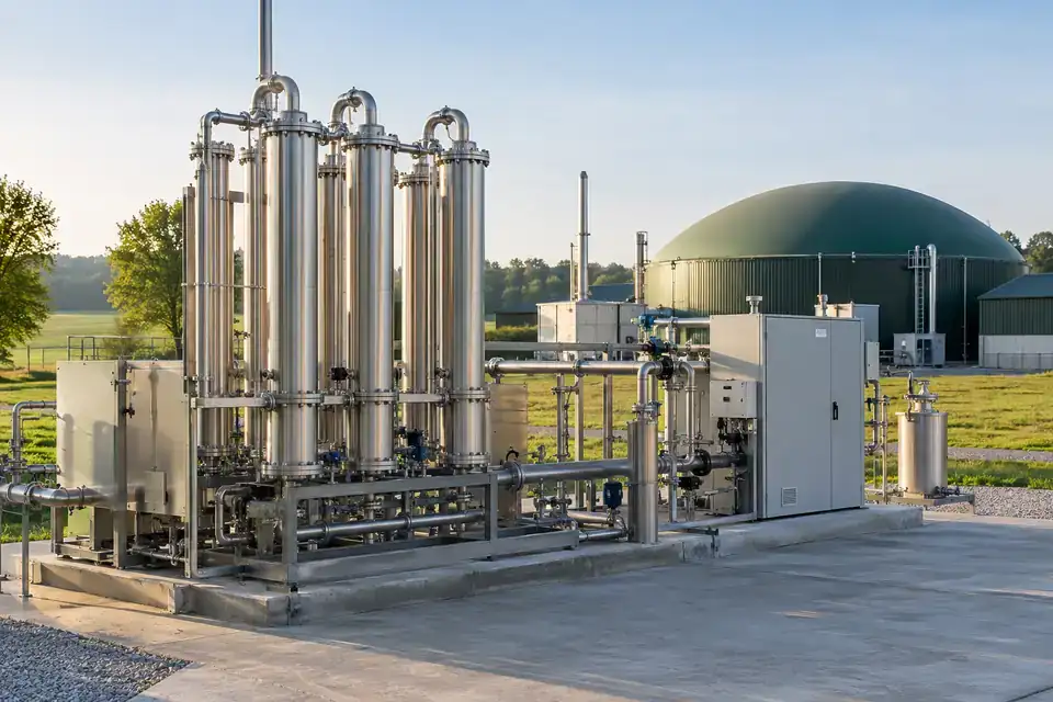
Measurements to observe
H2S and CH4 concentrations at their specified ambient monitoring points.
Monitoring point
Candidate points around assessed sour-gas valve, connection and service-equipment release locations.
Placement & installation
Confirm materials, environmental limits, hazardous-area approval and inlet arrangement for the actual service conditions. Coordinate installation and servicing with the refinery’s approved work procedure.
Project details
Sour-gas composition, detection objectives, units and ranges, area classification, exposure conditions, warning response and integration.
Discuss this application

Biomethane upgrading and injection skids

CH4 concentration and, where specified, CO2 concentration as separate measurement tasks.
Biomethane upgrading and injection skid with gas treatment equipment and interconnected process manifolds
Biomethane upgrading and injection skids · Illustrative application image

Monitor the gas-service area around a biomethane upgrading or injection skid. A methane channel can be selected for the assessed combustible-gas task, and CO2 monitoring can be added where the upgrading process and site assessment identify a separate need. Specify each channel’s purpose and location so the readings support the facility’s own operating and inspection workflow.
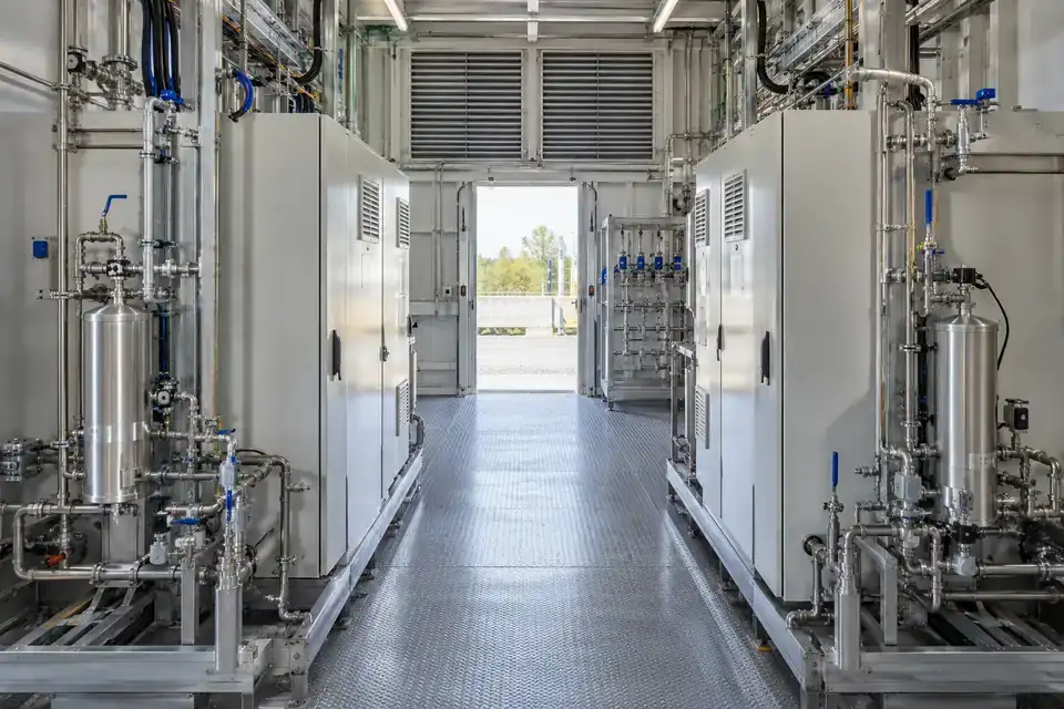
Measurements to observe
CH4 concentration and, where specified, CO2 concentration as separate measurement tasks.
Monitoring point
Assessed connections, manifolds and enclosure areas associated with upgrading and gas injection.
Placement & installation
Review process streams, airflow and enclosure access before assigning detector positions. Confirm each channel’s range, gas inlet and approved equipment configuration for the installation.
Project details
Upgrading process, gas streams, selected channels, area classification, ventilation, local warning requirements, power and reporting.
Discuss this application
02Hydrogen systems & charging facilities5 monitoring tasks
Industrial hydrogen electrolyser service enclosure with water-electrolysis modules and gas utility connections
Hydrogen electrolyser service enclosures · Illustrative application image

Match a hydrogen-suitable channel to the equipment, ventilation and potential release conditions. Oxygen monitoring, where required, is a separate concentration task with its own purpose and location.

Hydrogen electrolyser service enclosures

H2 concentration; O2 concentration by volume where separately specified.
Industrial hydrogen electrolyser service enclosure with water-electrolysis modules and gas utility connections
Hydrogen electrolyser service enclosures · Illustrative application image

Monitor hydrogen at selected points around an electrolyser service enclosure. Oxygen monitoring can be specified as a separate channel where the project requires an oxygen-atmosphere assessment. Identify the actual gas streams, potential release locations and ventilation design, then choose the sensing technology, range and alarm requirements for each point rather than treating both gases as one measurement.
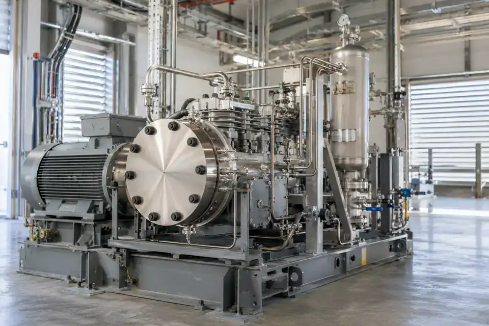
Measurements to observe
H2 concentration; O2 concentration by volume where separately specified.
Monitoring point
Candidate positions around assessed hydrogen connections and the separately identified oxygen monitoring area.
Placement & installation
Coordinate placement with enclosure airflow, release behaviour, electrical classification and the equipment supplier’s access requirements. Select a hydrogen-suitable sensing principle and approved installation assembly.
Project details
Electrolyser layout, gas streams, H2 / O2 tasks by point, ventilation, zone documentation, local warnings, supply and platform.
Discuss this application

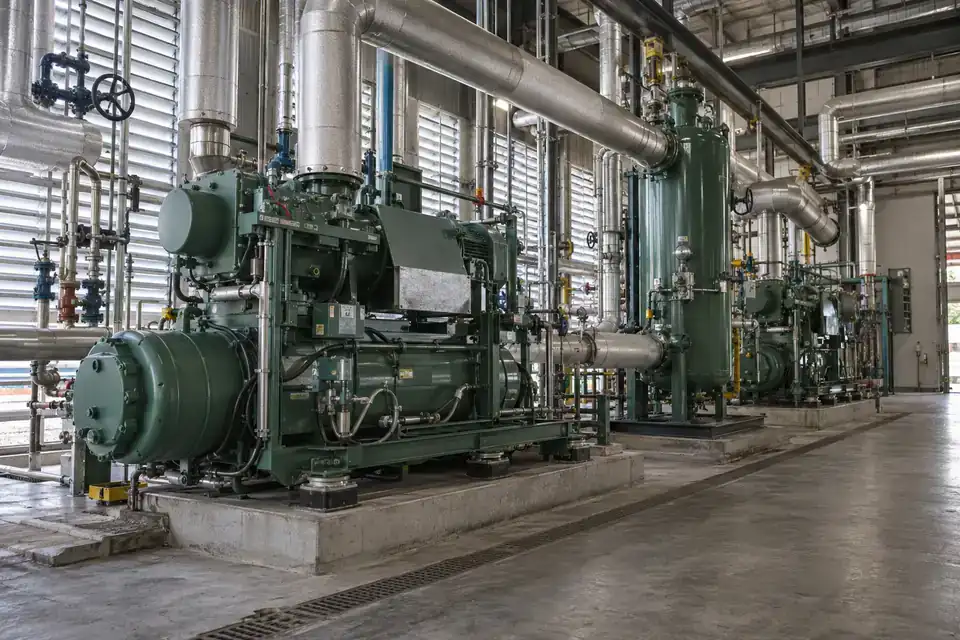
Hydrogen compression equipment

H2 concentration in the ambient monitoring areas defined for the compressor equipment.
Hydrogen compression equipment with a compact industrial compressor and high-pressure gas manifolds
Hydrogen compression equipment · Illustrative application image

Monitor hydrogen concentrations around the assessed service points of a compression installation. Concentration trends and configured notifications can help the operating team review equipment events alongside maintenance records. Define the potential release sources and airflow before assigning detector locations, then agree a hydrogen-capable channel, its measurement range and the complete local and remote warning workflow.
Measurements to observe
H2 concentration in the ambient monitoring areas defined for the compressor equipment.
Monitoring point
Candidate locations around assessed compressor seals, fittings, manifolds and enclosure pockets.
Placement & installation
Consider ventilation, release pressure, obstructions and access when planning coverage. Confirm the hydrogen sensing principle, approval, gas inlet and 9–24V electrical arrangement for the supplied configuration.
Project details
Hydrogen service conditions, compressor arrangement, release assessment, range and units, classified area, alarm response and data path.
Discuss this application

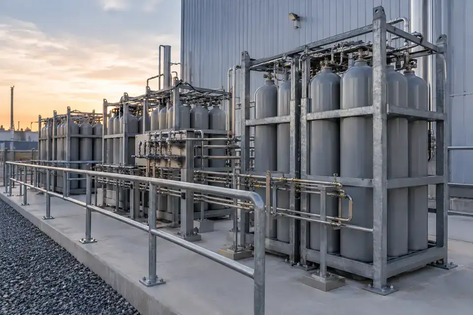
Hydrogen storage and transfer manifolds

H2 concentration around specified storage and transfer connection areas.
Hydrogen storage and transfer manifold installation with organized cylinder banks and gas connection pipework
Hydrogen storage and transfer manifolds · Illustrative application image

Observe hydrogen at monitoring points associated with storage and transfer manifolds. The concentration task is selected around actual connections, transfer routines and the site’s assessed release locations. Agree the required gas channel and units with the operating team, then define detector coverage, electrical installation, warning interfaces and the receiving platform as one project configuration.
Measurements to observe
H2 concentration around specified storage and transfer connection areas.
Monitoring point
Candidate locations around assessed manifold valves, joints and transfer connections.
Placement & installation
Review release direction, enclosure geometry, ventilation and service access. Match detector and cable-entry approval to the documented location, with protected 9–24V supply routing.
Project details
Storage / transfer arrangement, connection map, pressure conditions, ventilation, area classification, monitoring range and warning interfaces.
Discuss this application

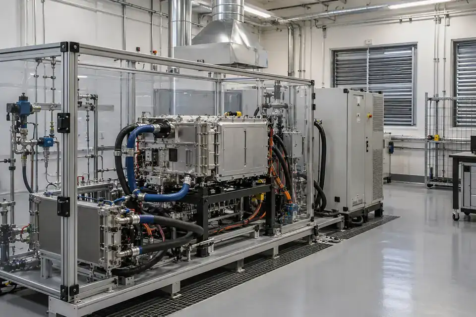
Fuel-cell and hydrogen test bays

H2 concentration at monitoring points defined for the active test arrangement.
Industrial fuel-cell and hydrogen test bay with a test rig, gas utility panel and service connections
Fuel-cell and hydrogen test bays · Illustrative application image

Monitor hydrogen in the defined service areas of a fuel-cell or hydrogen test bay. Test arrangements can change, so document the current gas connections, enclosure ventilation and detector coverage before each approved setup. Specify the concentration range, local warning requirements and data records needed for the test programme, with installation and response arrangements agreed by the responsible team.
Measurements to observe
H2 concentration at monitoring points defined for the active test arrangement.
Monitoring point
Candidate positions around assessed supply connections, test enclosures and gas-handling service points.
Placement & installation
Coordinate detectors with test-bay airflow, movable equipment and approved access. Confirm the hydrogen channel, relevant equipment approval, power and signal interfaces for the configuration.
Project details
Test gases, current rig layout, release assessment, ventilation, measurement range, local warning / control interfaces and data records.
Discuss this application

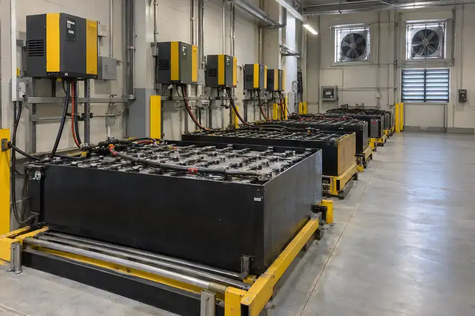
Lead-acid battery charging rooms

H2 concentration at the monitoring points defined for the lead-acid charging area.
Industrial lead-acid battery charging room with large battery banks, chargers and visible ventilation equipment
Lead-acid battery charging rooms · Illustrative application image

Monitor hydrogen where a facility assessment identifies release during lead-acid battery charging. The gas task should be defined around the batteries, charging programme and room ventilation, giving facilities staff a concentration reference within the agreed operating procedure. Select a hydrogen-suitable channel and specify how local warnings and remote notifications are coordinated with the charging-area response.
Measurements to observe
H2 concentration at the monitoring points defined for the lead-acid charging area.
Monitoring point
Candidate locations chosen from battery positions, possible accumulation areas and the ventilation assessment.
Placement & installation
Plan placement with airflow, room obstructions, electrical classification and charging-equipment access. Confirm the sensing principle, power routing, alarm interfaces and practical calibration access.
Project details
Battery type and arrangement, charging schedule, ventilation design, area assessment, gas range, warning response and platform.
Discuss this application
03Ammonia refrigeration & transfer5 monitoring tasks
Ammonia refrigeration machinery room with industrial compressors and recognizable refrigerant service pipework
Ammonia refrigeration machinery rooms · Illustrative application image

Plan ammonia monitoring around refrigeration or transfer equipment and its service environment. Specify the NH3 range, exposure conditions and local warning workflow for each assessed point.

Ammonia refrigeration machinery rooms

NH3 concentration at specified ambient monitoring points in the machinery room.
Ammonia refrigeration machinery room with industrial compressors and recognizable refrigerant service pipework
Ammonia refrigeration machinery rooms · Illustrative application image

Monitor ammonia at selected points within a refrigeration machinery room. The detection layout is planned around the actual plant, assessed release sources and room ventilation, so each channel has a clear purpose and serviceable location. Specify the NH3 range and the required warning response with the refrigeration team, then agree the detector assembly, external supply and reporting integration.
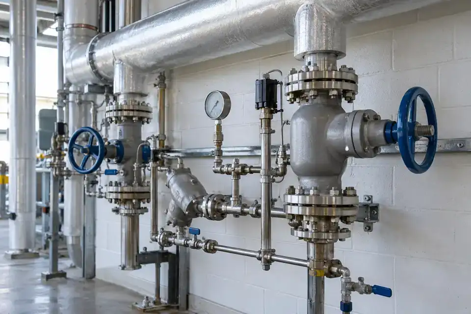
Measurements to observe
NH3 concentration at specified ambient monitoring points in the machinery room.
Monitoring point
Candidate positions around assessed compressors, valve groups and accessible refrigeration connections.
Placement & installation
Review air movement, temperature, moisture and maintenance access when locating detectors. Confirm ammonia-channel suitability, hazardous-area requirements, gas inlet protection and cable-entry conditions.
Project details
Refrigerant, machinery-room layout, release assessment, temperature, ventilation, NH3 range, local warnings, supply and platform.
Discuss this application

Refrigeration valve and service stations

NH3 concentration around the selected refrigeration valve and service station.
Industrial refrigeration valve station with insulated pipes, service valves and accessible maintenance space
Refrigeration valve and service stations · Illustrative application image

Observe ammonia around valve and service stations on an industrial refrigeration system. A defined point-monitoring task helps the team associate concentration readings with service work and operating events. Identify the actual refrigerant and assessed release points, then select detector locations and a warning workflow that fit the station’s enclosure, ventilation and maintenance access.
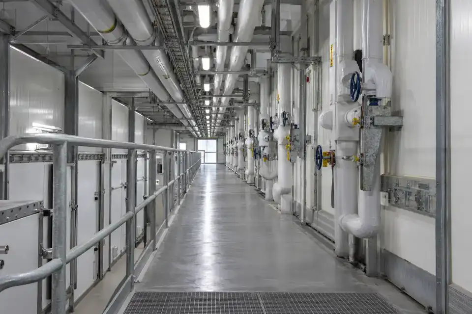
Measurements to observe
NH3 concentration around the selected refrigeration valve and service station.
Monitoring point
Candidate locations around assessed valve-group joints, service connections and enclosure areas.
Placement & installation
Plan gas exposure and access around airflow, cold surfaces, condensation and servicing. Confirm the selected detector’s environmental and approval requirements along with the external supply arrangement.
Project details
Valve-station drawing, ammonia service conditions, temperature / condensation, measurement range, area classification and notification workflow.
Discuss this application

Cold-store refrigeration service corridors

NH3 concentration around specified refrigeration service equipment and connections.
Cold-storage refrigeration service corridor with insulated refrigerant pipes and accessible valve connections
Cold-store refrigeration service corridors · Illustrative application image

Monitor the assessed ammonia release task along a cold-store refrigeration service corridor. This concerns the refrigerant service equipment and connecting pipework rather than the room’s temperature or food-storage environment. Define the coverage and operating conditions with the refrigeration team, then select the NH3 channel, detector placement, local warning requirements and remote reporting path for that area.
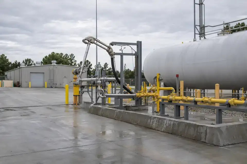
Measurements to observe
NH3 concentration around specified refrigeration service equipment and connections.
Monitoring point
Candidate locations near assessed pipe and valve connections within the service corridor.
Placement & installation
Review airflow, low temperatures, condensation, access and cleaning exposure. Match the detector configuration, sampling arrangement, approval and power routing to the actual installation conditions.
Project details
Service-corridor layout, refrigerant connections, environmental conditions, detection range, warning response, 9–24V supply and platform.
Discuss this application

Ammonia unloading and transfer areas

NH3 concentration at selected unloading and transfer monitoring points.
Industrial ammonia unloading and transfer area with a receiving manifold and bulk-transfer connection equipment
Ammonia unloading and transfer areas · Illustrative application image

Monitor ammonia around the defined unloading and transfer connections at an industrial receiving point. The site’s transfer procedure and release assessment establish which monitoring points and concentration ranges are useful. Coordinate detector coverage with vehicle positioning, connection work and airflow, then agree the local warning and remote reporting requirements for the supplied configuration.
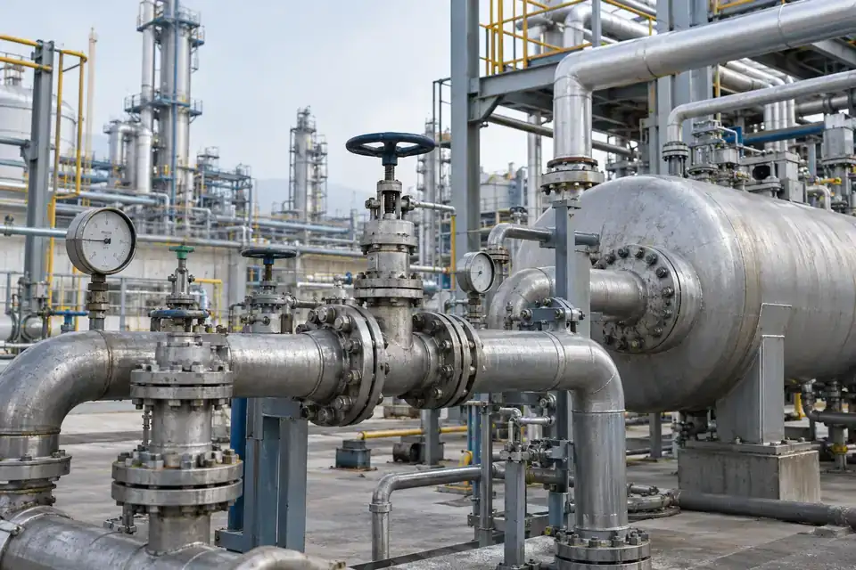
Measurements to observe
NH3 concentration at selected unloading and transfer monitoring points.
Monitoring point
Candidate positions around assessed hose, coupling, valve and receiving-manifold connections.
Placement & installation
Plan detector exposure, mechanical protection and service access around transfer operations. Confirm the relevant approval, environmental limits, electrical supply and alarm-interface requirements for the location.
Project details
Ammonia form and service conditions, transfer layout, connection routine, area classification, detection range and warning response.
Discuss this application

Fertilizer-plant ammonia service areas

NH3 concentration at assessed ambient monitoring points around ammonia service equipment.
Fertilizer-plant ammonia service area with process pipes, valves and accessible industrial service platforms
Fertilizer-plant ammonia service areas · Illustrative application image

Observe ammonia at defined service points around a fertilizer plant’s ammonia equipment. The monitored gas and range are selected from the actual process and release assessment, giving operators a concentration reference alongside plant procedures. Describe the local environment, enclosure and access conditions so detector construction, placement and integration can be reviewed for that particular service area.
Measurements to observe
NH3 concentration at assessed ambient monitoring points around ammonia service equipment.
Monitoring point
Candidate locations near identified valve groups, connections and process-service release points.
Placement & installation
Confirm gas conditions, temperature, contamination, ventilation and hazardous-area equipment requirements. Provide approved mounting, cable entries and access for inspection and response checks.
Project details
Ammonia process stage, release locations, environmental conditions, gas range, area classification, local warnings, supply and platform.
Discuss this application
04Wastewater treatment & biogas facilities5 monitoring tasks
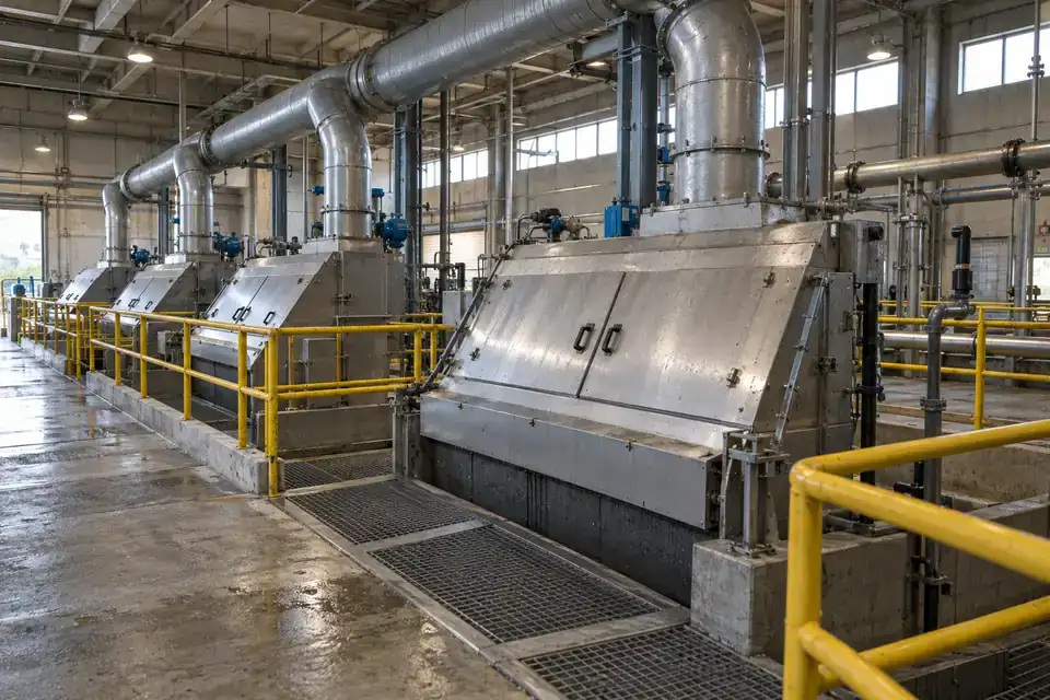
Wastewater headworks with screening equipment, covers, ventilation ducts and industrial service walkways
Wastewater inlet and screening areas · Illustrative application image

Follow the gas tasks associated with treatment equipment and biogas handling. Define each channel, sampling location and access procedure alongside moisture, ventilation and service requirements.

Wastewater inlet and screening areas

H2S concentration at specified ambient monitoring points around inlet and screening equipment.
Wastewater headworks with screening equipment, covers, ventilation ducts and industrial service walkways
Wastewater inlet and screening areas · Illustrative application image

Monitor hydrogen sulfide at selected points around wastewater inlet and screening operations. The task focuses on the gas conditions identified in the facility assessment and how operators review changes during the working day. Define detector locations around the equipment, ventilation and access arrangement, then agree the H2S range, warning response and data path for the chosen configuration.
Measurements to observe
H2S concentration at specified ambient monitoring points around inlet and screening equipment.
Monitoring point
Candidate positions around assessed screening channels, covered inlet equipment and service areas.
Placement & installation
Account for moisture, contaminants, airflow and cleaning access. Confirm the gas inlet, materials, environmental limits and relevant electrical / area requirements for the supplied detector.
Project details
Headworks layout, expected gas sources, humidity and fouling, ventilation, detection range, local warnings and platform.
Discuss this application

Wet-well service and access areas

H2S and CH4 concentrations; O2 by volume where included in the project.
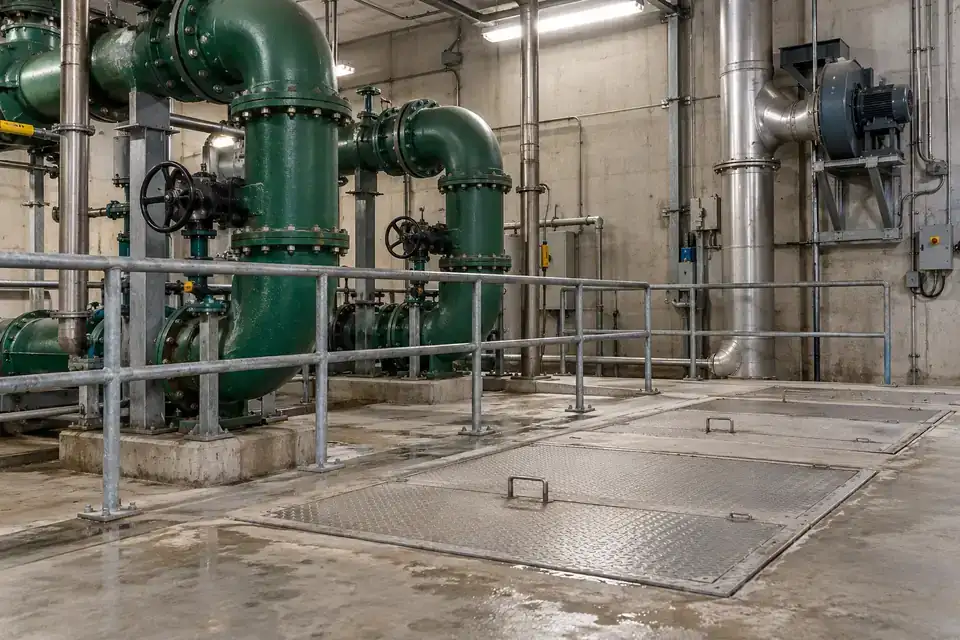
Wastewater wet-well service area with access covers, gas ventilation pipework and a maintained pump-station interior
Wet-well service and access areas · Illustrative application image

Monitor the selected gas conditions at wet-well service and access areas. H2S, CH4 and oxygen can represent different tasks, so specify each required channel and monitoring point from the site assessment. Readings support the agreed facilities workflow, while entry preparation, portable checks and response arrangements remain part of the site’s documented operating procedure.
Measurements to observe
H2S and CH4 concentrations; O2 by volume where included in the project.
Monitoring point
Candidate positions around assessed wet-well gas sources, access zones and ventilated service spaces.
Placement & installation
Define sampling location and representative exposure with the ventilation and access plan. Confirm channel-specific technology, condensation management, approval, power and warning interfaces for the installation.
Project details
Access / entry procedure, selected gases, sampling points, ventilation, humidity, area classification, local warnings and reporting.
Discuss this application

Sludge-handling and dewatering rooms

H2S concentration at selected sludge-handling and dewatering service points.
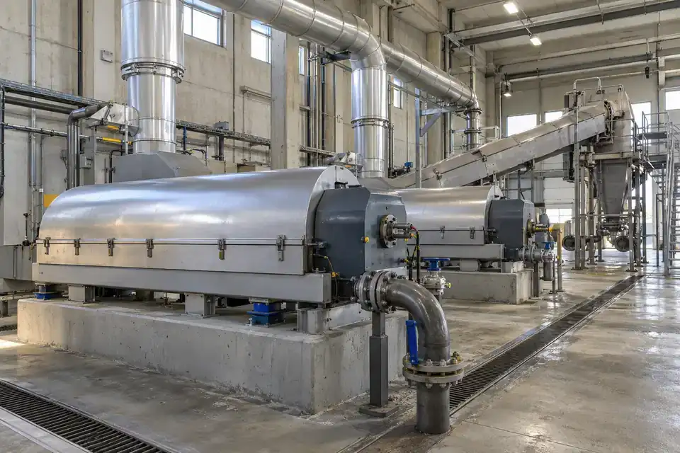
Industrial sludge-handling room with dewatering equipment, covered transfers and ventilation services
Sludge-handling and dewatering rooms · Illustrative application image

Observe hydrogen sulfide around a sludge-handling or dewatering room where the process assessment identifies a gas-monitoring task. Define release sources, equipment enclosure and airflow, then select the H2S channel and warning workflow for the environment. Time-stamped readings can be reviewed alongside handling schedules and service records, with practical access for inspection and sensor checks.
Measurements to observe
H2S concentration at selected sludge-handling and dewatering service points.
Monitoring point
Candidate positions around assessed handling equipment, transfer points and occupied service areas.
Placement & installation
Review ventilation, moisture, contamination and washdown exposure. Confirm inlet protection and calibration access with the detector’s environmental limits, approved installation and external supply routing.
Project details
Sludge process, equipment layout, gas-source assessment, humidity, washdown, H2S range, local warnings and platform.
Discuss this application

Digester gas-treatment skids

CH4, H2S and CO2 concentrations as individually specified monitoring tasks.
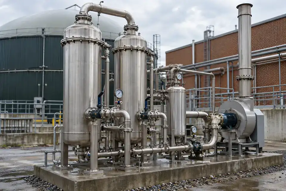
Digester gas-treatment skid with gas cleanup vessels, condensate management and interconnected gas service pipes
Digester gas-treatment skids · Illustrative application image

Monitor selected gases around a digester gas-treatment skid and its service connections. CH4, H2S and CO2 channels are chosen for distinct concentration tasks based on the actual gas stream and assessed release locations. Agree the detector coverage and units per channel, then coordinate local warnings, service access and remote records with the plant’s operating procedure.
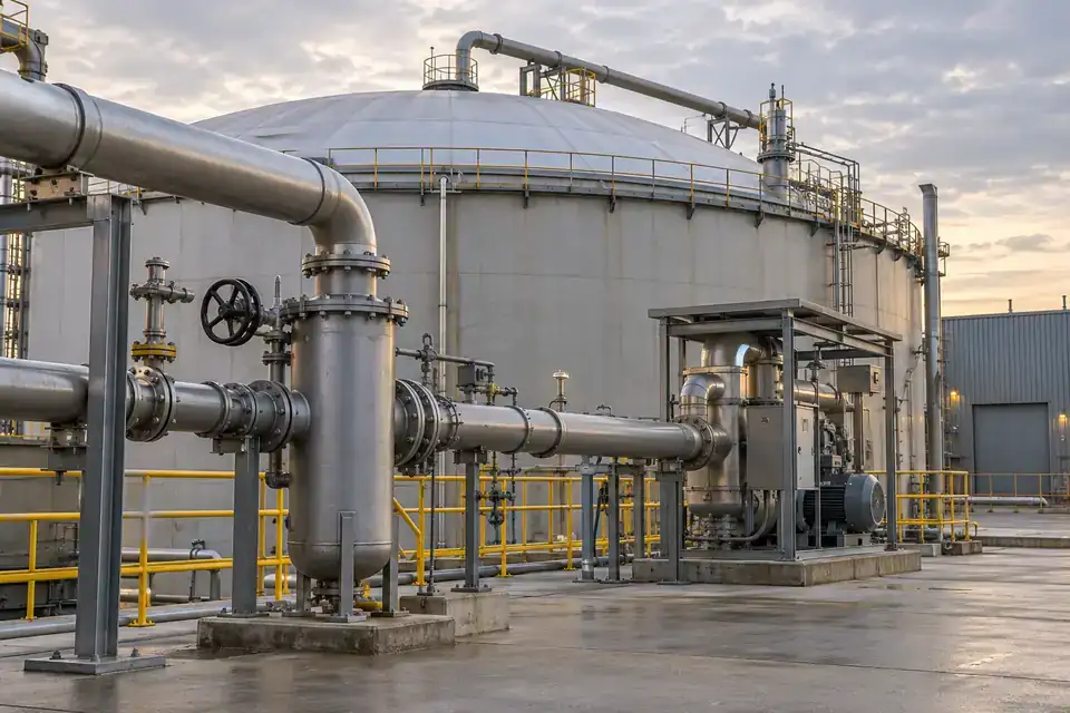
Measurements to observe
CH4, H2S and CO2 concentrations as individually specified monitoring tasks.
Monitoring point
Candidate positions around assessed gas-treatment connections, valves and enclosure service areas.
Placement & installation
Confirm whether each task uses ambient diffusion or an engineered sampling path. Review moisture, contaminants, airflow, relevant approval and accessible inspection for the selected assembly.
Project details
Digester-gas composition, selected gas tasks, range and units, sampling method, area classification, supply and warning interfaces.
Discuss this application

Industrial anaerobic-treatment facilities

CH4 and H2S concentrations at the specified anaerobic-treatment monitoring points.
Industrial anaerobic wastewater-treatment facility with covered process vessels, gas pipework and service access
Industrial anaerobic-treatment facilities · Illustrative application image

Monitor gas conditions identified around an industrial anaerobic-treatment installation. Methane and hydrogen sulfide can be specified as separate tasks at assessed gas-handling and service points. Define the process streams, ventilation and access conditions with the treatment team, then select the detector configuration and warning workflow around the real environment and intended operating response.
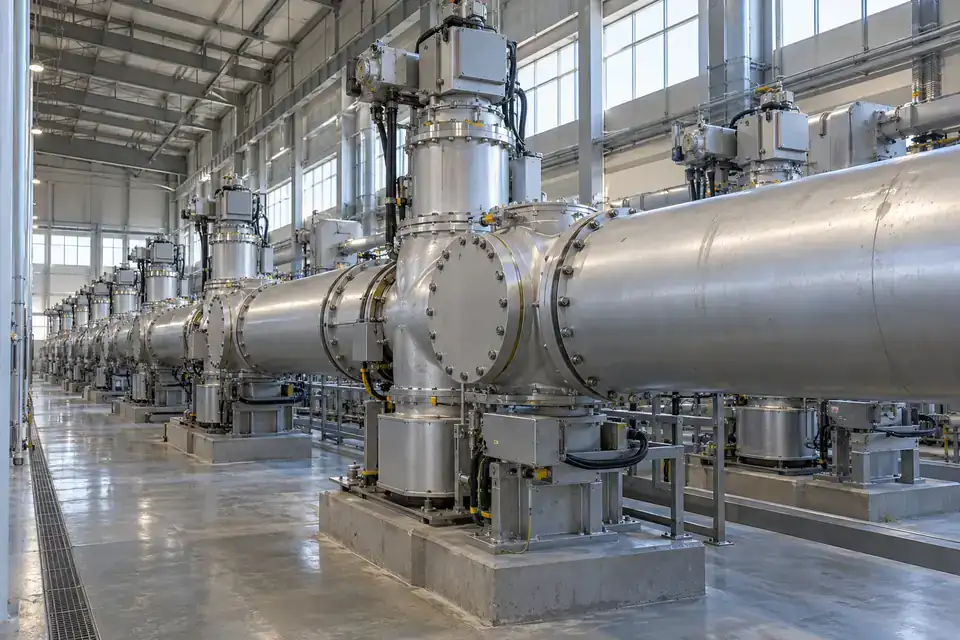
Measurements to observe
CH4 and H2S concentrations at the specified anaerobic-treatment monitoring points.
Monitoring point
Candidate locations around assessed gas connections, covered process equipment and accessible service areas.
Placement & installation
Review moisture, gas contaminants, airflow and maintenance access. Confirm each channel’s sensing principle, sampling arrangement, approval, external supply and integration requirements for the location.
Project details
Treatment process, gas composition, release assessment, target ranges, ventilation, area classification, local warnings and receiving platform.
Discuss this application
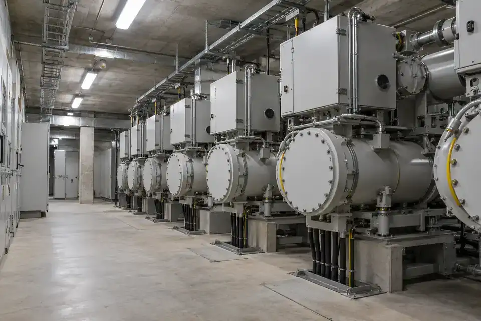
05SF6-insulated electrical equipment5 monitoring tasks
Indoor gas-insulated switchgear hall with enclosed switchgear bays, service aisles and industrial electrical equipment
Indoor gas-insulated switchgear halls · Illustrative application image

Monitor ambient SF6 where the project identifies a leakage task around electrical equipment. Define any oxygen-atmosphere task separately, with representative sampling and access for checks.

Indoor gas-insulated switchgear halls

Ambient SF6 concentration and, where specified, O2 deficiency monitoring.
Indoor gas-insulated switchgear hall with enclosed switchgear bays, service aisles and industrial electrical equipment
Indoor gas-insulated switchgear halls · Illustrative application image

Follow ambient SF6 concentration around indoor gas-insulated switchgear, with a separate O2 channel where the risk assessment calls for oxygen-deficiency monitoring. A gas escape can displace breathing air even though SF6 is nonflammable. Define monitoring points around likely releases and room airflow, then agree local warning requirements, remote reporting and access for inspection with the supplied configuration.
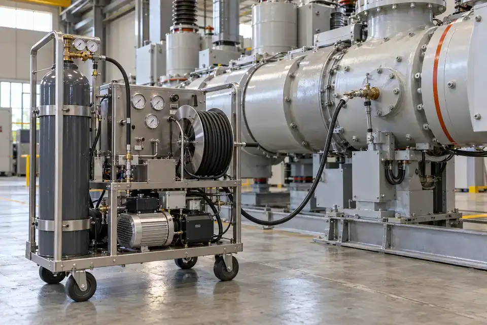
Measurements to observe
Ambient SF6 concentration and, where specified, O2 deficiency monitoring.
Monitoring point
Candidate points near SF6 equipment and relevant room accumulation or occupied areas.
Placement & installation
Assess releases, gas movement and ventilation before placing points; keep the gas inlet, external power connection and service access practical.
Project details
Equipment layout, SF6 inventory, ventilation, access routes, O2 duty, external power and alarm requirements.
Discuss this application

SF6 handling and filling areas

Ambient SF6 concentration during gas handling and filling duties.
Industrial SF6 gas filling station with secured cylinders, a gas-handling cart, hoses and a clean service aisle
SF6 handling and filling areas · Illustrative application image

Bring ambient SF6 readings into the working routine around gas filling and handling equipment. Connection changes, valves and transfer operations are candidate release sources to assess against the gas inventory and ventilation. Select direct gas-concentration monitoring for the room, define the warning and reporting workflow, and include accessible calibration points and external power in the project configuration.
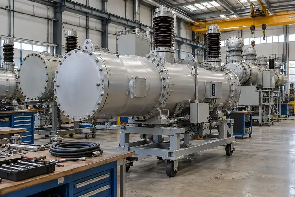
Measurements to observe
Ambient SF6 concentration during gas handling and filling duties.
Monitoring point
Candidate locations around filling connections, valves and equipment service spaces.
Placement & installation
Review gas movement, room ventilation and transfer activity; select accessible points with a suitable gas inlet and documented power routing.
Project details
Filling method, connection layout, expected releases, ventilation, ambient conditions, measuring range and warning needs.
Discuss this application

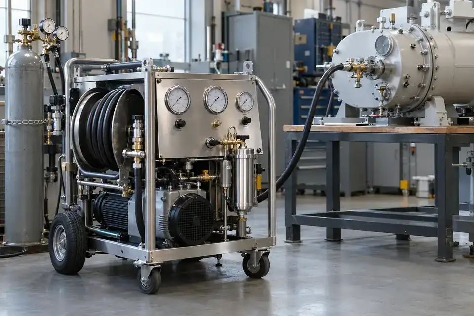
Switchgear maintenance workshops

Ambient SF6 concentration around the defined maintenance operations.
Electrical switchgear maintenance workshop with a switchgear assembly, service bench and SF6 recovery equipment
Switchgear maintenance workshops · Illustrative application image

Monitor the ambient SF6 condition in workshops that service gas-insulated electrical equipment. Opening equipment connections and managing recovery or refill operations create different potential release paths from normal installed service. Define the actual workshop gas inventory and work sequence, then select concentration ranges, candidate points and reporting requirements around ventilation, occupied work areas and routine access for testing.
Measurements to observe
Ambient SF6 concentration around the defined maintenance operations.
Monitoring point
Candidate monitoring points beside gas-service benches and relevant workshop release paths.
Placement & installation
Assess handling steps, gas dispersion and ventilation; maintain safe access for function testing and route external power around workshop activity.
Project details
Equipment types, recovery and refill sequence, gas inventory, workshop airflow, occupied areas and service plan.
Discuss this application

Electrical basement service rooms

Ambient SF6 concentration plus the separately specified O2 measurement duty.
Industrial electrical basement with gas-insulated equipment, cable routes, ventilation ducts and a clear service walkway
Electrical basement service rooms · Illustrative application image

Assess ambient gas conditions in basement rooms containing SF6 equipment or a credible gas ingress path. SF6 can displace oxygen, so direct concentration measurement and a separate O2 duty may both be relevant to the site assessment. Review low-lying spaces, room circulation and access routes together, then define the supplied channels, warning locations and maintenance access for the complete installation.
Measurements to observe
Ambient SF6 concentration plus the separately specified O2 measurement duty.
Monitoring point
Candidate points near gas equipment, identified ingress paths and relevant enclosed areas.
Placement & installation
Use the site assessment to evaluate gas movement and ventilation; plan warning access, external power and service routes before commissioning.
Project details
Basement layout, actual SF6 sources, ingress routes, ventilation, access needs, O2 duty and local warning requirements.
Discuss this application

SF6 recovery and equipment-test facilities

Ambient SF6 concentration around recovery and equipment-testing activities.
SF6 recovery and electrical testing facility with a recovery cart, secured gas cylinders and a switchgear test assembly
SF6 recovery and equipment-test facilities · Illustrative application image

Add ambient SF6 monitoring around recovery equipment and electrical test facilities that handle the gas. The room measurement addresses gas reaching the workspace, while sealed-equipment density or gas-quality measurements serve a different task. Define recovery connections, filling steps and possible releases, then select the concentration channel, candidate monitoring points and alarm workflow around the facility's ventilation and service access.
Measurements to observe
Ambient SF6 concentration around recovery and equipment-testing activities.
Monitoring point
Candidate points around recovery connections and the relevant test workspace.
Placement & installation
Review gas-handling steps, gas movement and ventilation; keep the selected point accessible and document the external supply and cable route.
Project details
Recovery equipment, gas inventory, test sequence, transfer connections, room airflow, measuring duty and reporting needs.
Discuss this application
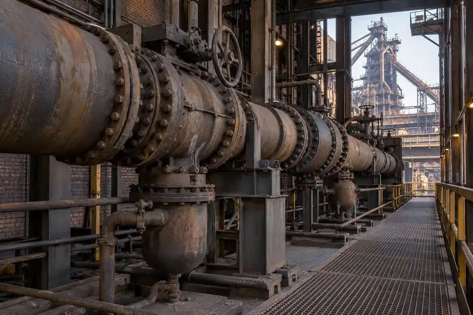
06Metals, combustion & process gas5 monitoring tasks
Steelworks blast-furnace gas service gallery with large process pipes, valves and an accessible industrial walkway
Blast-furnace gas service galleries · Illustrative application image

Select channels for the actual process gas and the monitoring purpose. Ambient leak detection, combustion-related monitoring and engineered process sampling require clearly defined configurations.

Blast-furnace gas service galleries

CO concentration for the defined toxic process-gas monitoring duty.
Steelworks blast-furnace gas service gallery with large process pipes, valves and an accessible industrial walkway
Blast-furnace gas service galleries · Illustrative application image

Follow the CO concentration around blast-furnace gas service equipment where the process inventory identifies a toxic release risk. A dedicated CO measurement channel helps the operating team review the selected points and required warnings. Define valves, connections, enclosed passages and occupied routes together, then confirm the measuring range, interference conditions, response path and service access for the actual gas-service arrangement.
Measurements to observe
CO concentration for the defined toxic process-gas monitoring duty.
Monitoring point
Candidate locations along identified valves, connections and relevant enclosed service passages.
Placement & installation
Assess release paths, gas movement and ventilation; position serviceable points using the selected detector's ambient limits and external power requirements.
Project details
Process-gas composition, CO duty, connection layout, ventilation, temperature, interference and required alarm response.
Discuss this application

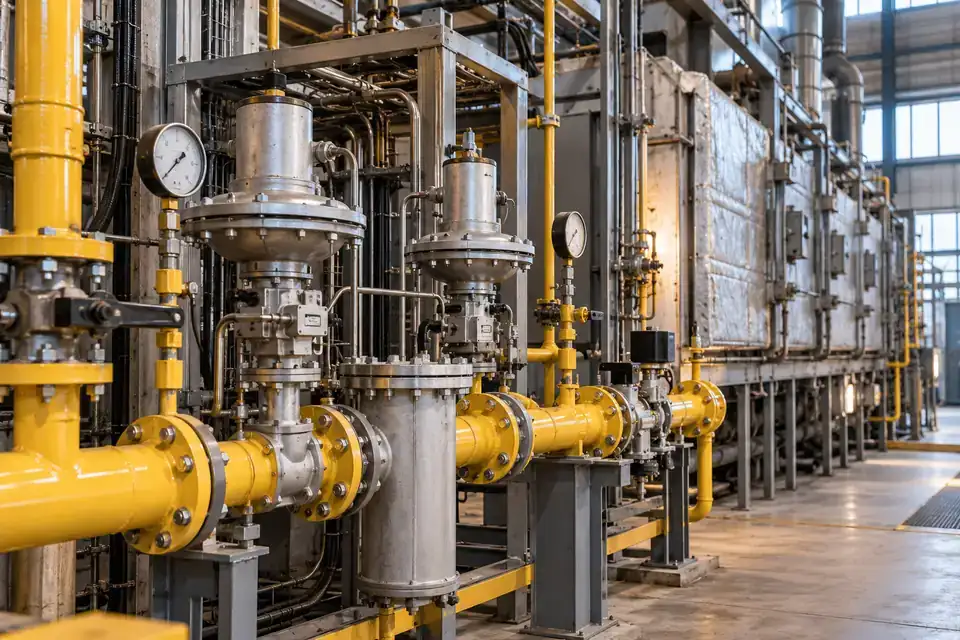
Industrial furnace gas-service areas

CH4 combustible-gas duty and a separately defined CO toxic-gas duty.
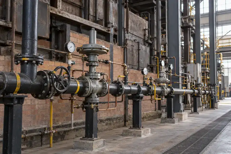
Industrial furnace service area with natural-gas burner pipework, valves, furnace equipment and a maintenance aisle
Industrial furnace gas-service areas · Illustrative application image

Distinguish fuel-gas leakage from toxic CO conditions around an industrial furnace. CH4 monitoring may address the selected natural-gas supply, while a separate CO channel addresses the specified combustion or process release. Share the fuel and process details, probable leak points and occupied areas so the channel arrangement, units, ranges and alarm response can be matched to the furnace service duty.
Measurements to observe
CH4 combustible-gas duty and a separately defined CO toxic-gas duty.
Monitoring point
Candidate points around fuel-gas connections and identified combustion or process-gas release paths.
Placement & installation
Assess gas movement, ventilation and hot surfaces; place serviceable points within the selected detector limits and confirm the power and wiring arrangement.
Project details
Fuel type, furnace process, gas connections, temperature, occupied routes, range units and local warning needs.
Discuss this application

Foundry fuel-gas supply areas

CH4 concentration for fuel-gas leakage and CO concentration for the specified toxic-gas duty.
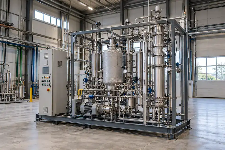
Foundry combustion service area with a metal-melting furnace, organized fuel-gas pipework and industrial ventilation
Foundry fuel-gas supply areas · Illustrative application image

Configure gas monitoring around the natural-gas supply and selected combustion-gas risks of a foundry. CH4 and CO address different decisions, so define each channel rather than treating one reading as a substitute for the other. Review burner connections, furnace surroundings, heat and airflow together, then specify candidate points and the required warning and data path for the operating team.
Measurements to observe
CH4 concentration for fuel-gas leakage and CO concentration for the specified toxic-gas duty.
Monitoring point
Candidate locations near gas-supply connections and assessed combustion-gas release areas.
Placement & installation
Review release direction, gas movement, ventilation and heat; provide service access and a documented external power feed for each selected point.
Project details
Foundry fuel system, combustion sources, ambient heat, airflow, gas units, warning requirements and maintenance access.
Discuss this application

Syngas process and pilot skids

CO toxic-gas measurement and H2 measurement selected for the combustible or low-concentration duty.
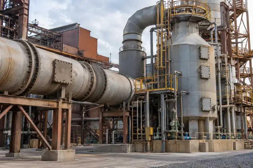
Industrial syngas pilot skid with process vessels, gas manifolds, instrument tubing and an accessible test area
Syngas process and pilot skids · Illustrative application image

Review the CO and H2 monitoring duties around a syngas process or pilot skid using the actual gas composition. Toxic CO and combustible hydrogen require gas-capable channels with ranges and units matched to their separate purposes. Define likely releases from connections and process equipment, then assess gas movement, oxygen conditions, interference and the local response requirements with the complete project configuration.
Measurements to observe
CO toxic-gas measurement and H2 measurement selected for the combustible or low-concentration duty.
Monitoring point
Candidate points around process connections, equipment enclosures and relevant occupied areas.
Placement & installation
Assess mixture behavior, gas movement and ventilation; select hydrogen-capable sensing and document the external power and hazardous-area wiring conditions.
Project details
Syngas composition, pressure and temperature, CO and H2 duties, area classification, interference and response requirements.
Discuss this application

Smelter sulfur-containing gas areas

SO2 concentration for the specified toxic process-gas duty.
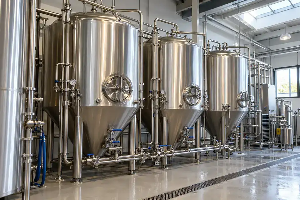
Metal smelter sulfur-gas service area with process ductwork, treatment equipment and an industrial maintenance platform
Smelter sulfur-containing gas areas · Illustrative application image

Select SO2 monitoring for smelting operations where sulfur-containing process gases can reach the workspace. The target duty is toxic-gas concentration at the chosen points, rather than a combustible-gas reading. Review the process inventory, fugitive release routes, hot gas behavior and ventilation, then define the SO2 range, interference review and warning workflow with practical access for calibration and inspection.
Measurements to observe
SO2 concentration for the specified toxic process-gas duty.
Monitoring point
Candidate locations around assessed sulfur-gas equipment and relevant workspace release paths.
Placement & installation
Assess process releases, gas movement, ventilation and heat; confirm ambient and corrosion limits and maintain service access with external power.
Project details
Smelting process, sulfur-gas sources, release temperature, ventilation, interference, measuring range and alarm needs.
Discuss this application
07Industrial CO2 & controlled-atmosphere areas5 monitoring tasks
Industrial fermentation service hall with stainless-steel process tanks, pipework and a clear utility walkway
Fermentation and process service areas · Illustrative application image

Define CO2 exposure monitoring around storage, use and release conditions. Pair the concentration task with site ventilation and the appropriate response; specify oxygen monitoring separately where required.

Fermentation and process service areas

Ambient CO2 concentration around the defined fermentation service duty.
Industrial fermentation service hall with stainless-steel process tanks, pipework and a clear utility walkway
Fermentation and process service areas · Illustrative application image

Follow CO2 conditions around industrial fermentation and associated process service spaces. Fermentation can produce elevated CO2 that creates a direct concentration hazard and can displace breathing air. Define ambient monitoring separately from process-vessel measurement or entry testing. Review release routes, room airflow and occupied areas, then select candidate points, warning access and calibration requirements for the site's operating routine.
Measurements to observe
Ambient CO2 concentration around the defined fermentation service duty.
Monitoring point
Candidate points along assessed releases and relevant occupied or adjoining enclosed spaces.
Placement & installation
Assess CO2 movement and ventilation; arrange warnings and service access for the monitored area and document the external power feed.
Project details
Fermentation layout, CO2 release routes, occupied areas, ventilation, concentration duty, warning access and calibration plan.
Discuss this application

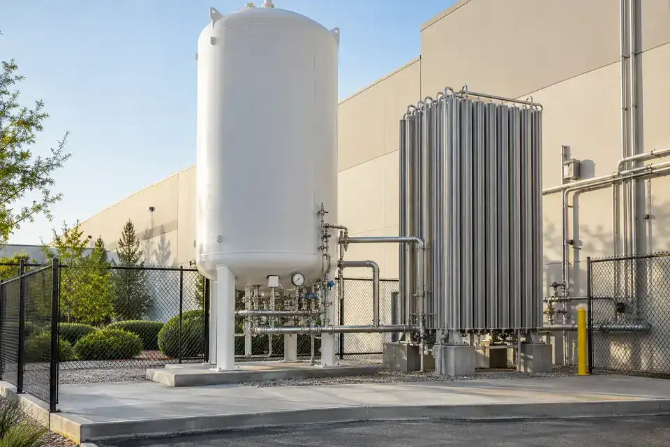
Beverage-plant CO2 storage areas

Ambient CO2 concentration around storage and transfer operations.
Beverage plant CO2 storage utility area with a storage vessel, valves, transfer pipework and industrial service access
Beverage-plant CO2 storage areas · Illustrative application image

Monitor ambient CO2 around storage and transfer equipment serving a beverage plant. Leaks can create an elevated concentration in nearby service areas, with release conditions and ventilation affecting where the gas travels. Define the storage arrangement and probable release sources, then confirm the measuring range, candidate points and warning workflow alongside external power, data reporting and access for inspection.
Measurements to observe
Ambient CO2 concentration around storage and transfer operations.
Monitoring point
Candidate points near assessed storage connections and relevant adjoining enclosed spaces.
Placement & installation
Review cold-release behavior, gas movement and ventilation; select accessible locations and route external power and cables for the supplied configuration.
Project details
Storage form and inventory, connection layout, release conditions, ventilation, occupied spaces and warning needs.
Discuss this application

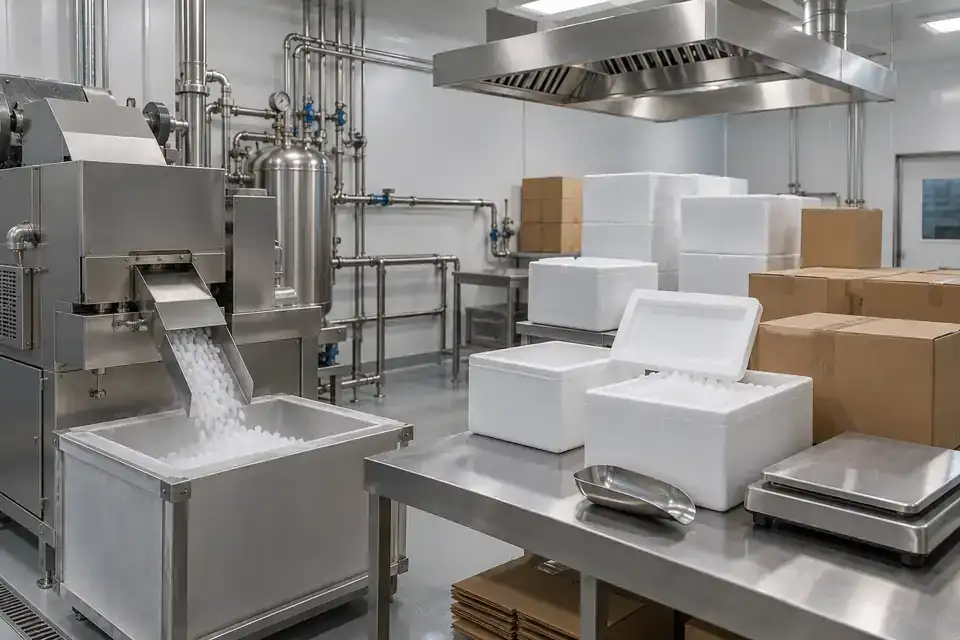
Dry-ice preparation and packing rooms

Direct CO2 concentration and, where specified, a separate O2 deficiency measurement.
Industrial dry-ice packing room with insulated containers, a packing bench and organized ventilation equipment
Dry-ice preparation and packing rooms · Illustrative application image

Assess CO2 buildup in rooms where dry ice is prepared or packed, using the actual quantities, work patterns and ventilation. Direct CO2 measurement addresses elevated concentration, while an O2 channel serves a separately defined deficiency duty. Select the required channels and monitoring points around releases and occupied work areas, then agree the local warning, reporting and service plan for the supplied system.
Measurements to observe
Direct CO2 concentration and, where specified, a separate O2 deficiency measurement.
Monitoring point
Candidate points around packing operations and relevant occupied or enclosed accumulation areas.
Placement & installation
Assess releases, gas movement and ventilation; keep the gas inlet and testing access practical and document external power and warning locations.
Project details
Dry-ice quantity, work sequence, room layout, airflow, CO2 and O2 duties, warning requirements and service access.
Discuss this application

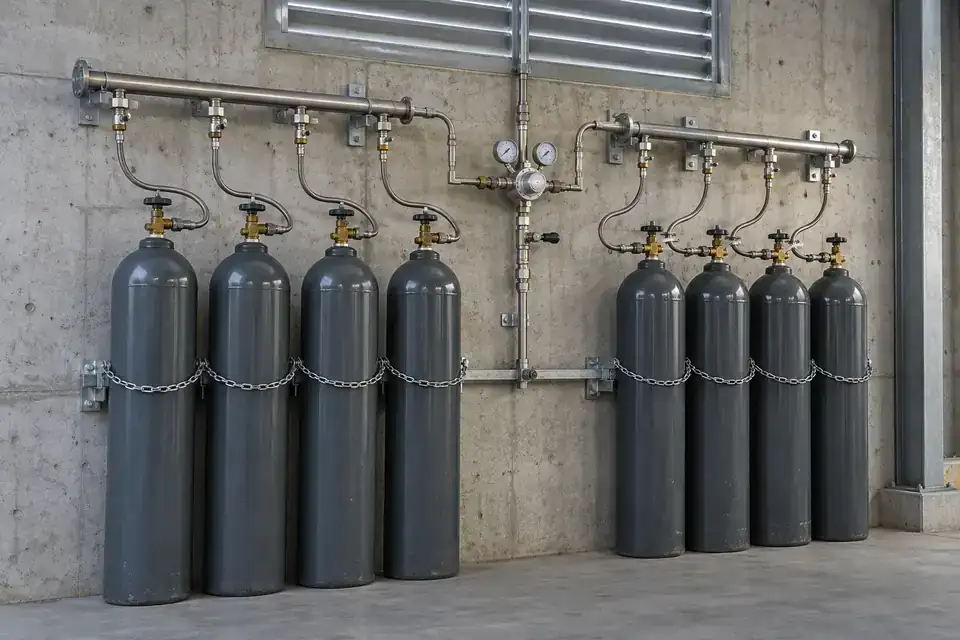
Industrial CO2 cylinder manifolds

Ambient CO2 concentration around the defined cylinder-manifold duty.
Industrial CO2 cylinder manifold with secured cylinders, pressure regulators, organized gas lines and a clear access aisle
Industrial CO2 cylinder manifolds · Illustrative application image

Bring ambient CO2 concentration into monitoring around an industrial cylinder manifold. Cylinder changes, regulators and connections identify possible release sources for the site review. Define the gas inventory, adjoining spaces and occupied routes, then assess ventilation and concentration requirements. Confirm candidate monitoring points, remote reporting and any required local warnings together with external power and access for routine function testing.
Measurements to observe
Ambient CO2 concentration around the defined cylinder-manifold duty.
Monitoring point
Candidate points around assessed regulators, manifold connections and relevant adjoining spaces.
Placement & installation
Review gas movement, ventilation and cylinder-handling activity; provide testing access and route external power without obstructing the service area.
Project details
Cylinder inventory, manifold layout, changeover method, airflow, occupied routes, concentration range and warning requirements.
Discuss this application

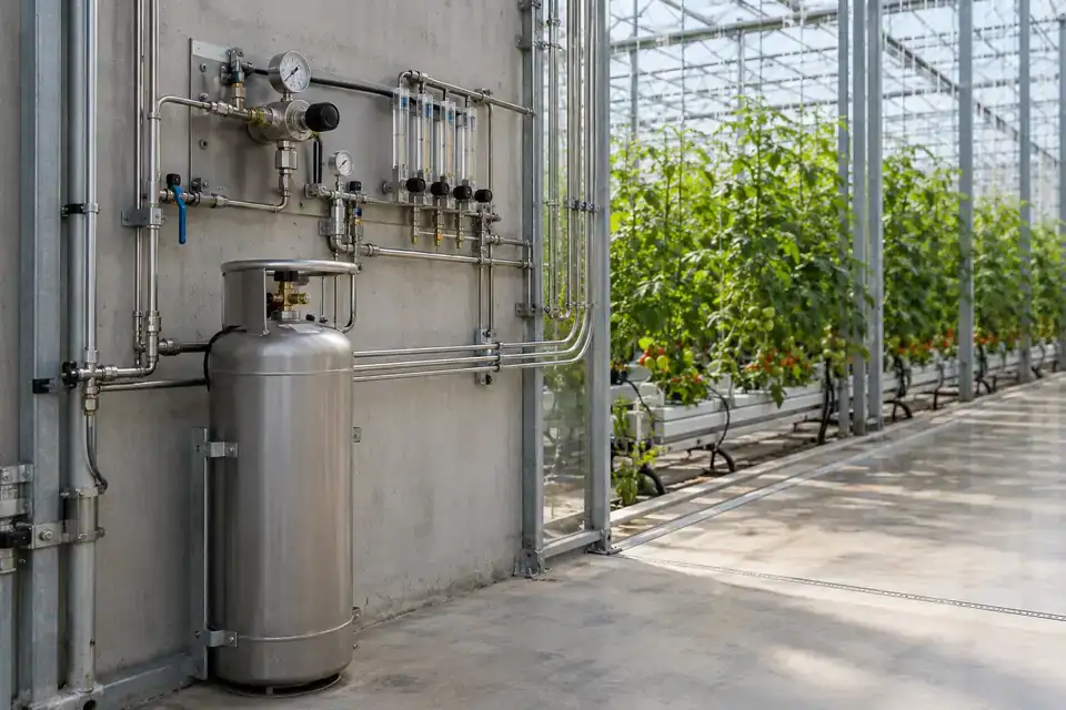
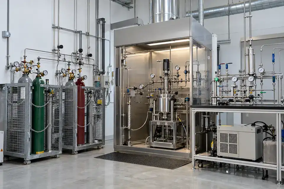
Greenhouse CO2 dosing utility areas

Ambient CO2 concentration around the specified gas utility and service spaces.
Greenhouse CO2 utility area with a gas dosing manifold, supply pipework and recognizable greenhouse structure in the background
Greenhouse CO2 dosing utility areas · Illustrative application image

Specify industrial CO2 monitoring around the dosing equipment and gas-service spaces supporting a greenhouse. The monitoring duty focuses on a credible release near the utility system and the people working there. Define the storage and dosing arrangement, enclosed equipment areas and ventilation, then select concentration ranges, candidate points and warning requirements separately from any crop-control measurement used by the growing operation.
Measurements to observe
Ambient CO2 concentration around the specified gas utility and service spaces.
Monitoring point
Candidate points near dosing connections and assessed enclosed utility areas.
Placement & installation
Assess release sources, gas movement and ventilation; position serviceable points and document external power, data routing and local warning needs.
Project details
CO2 supply type, dosing equipment, utility-space layout, occupied locations, ventilation and monitoring purpose.
Discuss this application
08Specialty gas & project-specific installations5 monitoring tasks
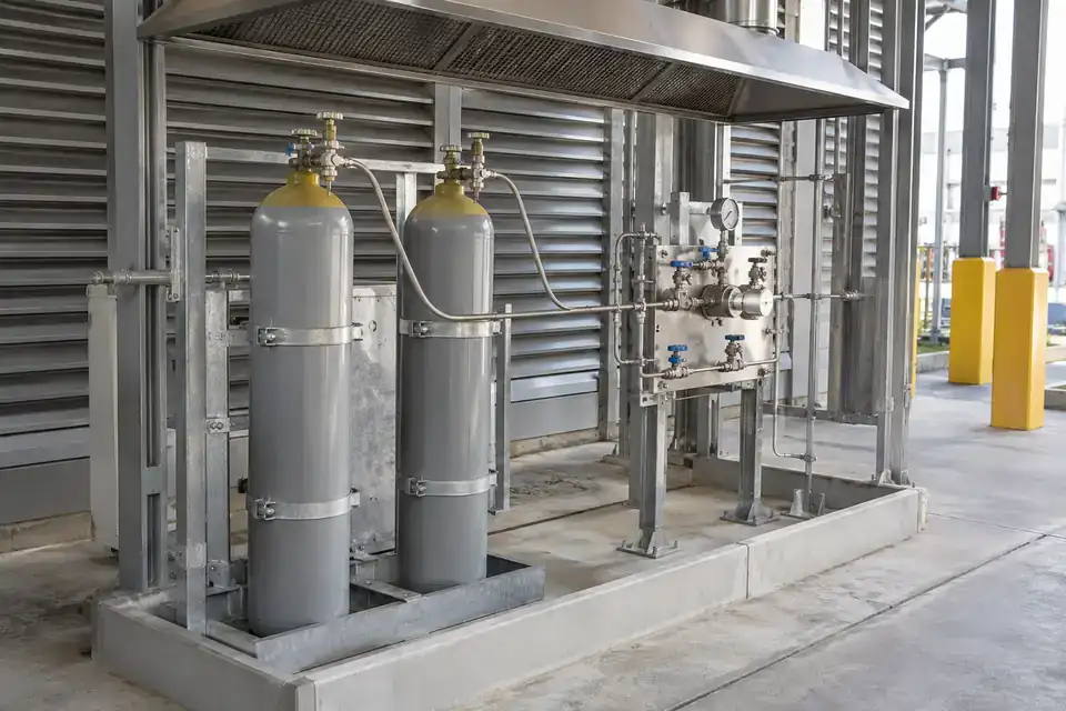
Industrial gas pilot laboratory with test skids, secured gas supplies, instrument tubing and an accessible work area
Industrial gas pilot and test laboratories · Illustrative application image

Bring the exact gas, process and installation requirements into one brief. Select gas channels, ranges, sampling and protection around the documented task, then agree integration and service needs.

Industrial gas pilot and test laboratories

H2 measurement for the specified combustible or low-concentration duty, plus CO toxic-gas measurement.
Industrial gas pilot laboratory with test skids, secured gas supplies, instrument tubing and an accessible work area
Industrial gas pilot and test laboratories · Illustrative application image

Configure separate H2 and CO monitoring duties around an industrial gas pilot or test laboratory. The gas inventory and experiment sequence determine possible releases, while enclosure airflow and occupied work areas shape the point assessment. Confirm hydrogen-capable sensing, CO-specific toxic measurement, interference and required ranges, then define the warning and reporting workflow alongside external power and practical access for testing.
Measurements to observe
H2 measurement for the specified combustible or low-concentration duty, plus CO toxic-gas measurement.
Monitoring point
Candidate points around assessed test enclosures, gas connections and occupied service areas.
Placement & installation
Review changing mixtures, gas movement and ventilation; select serviceable points and confirm power, wiring and applicable hazardous-area requirements.
Project details
Experimental gas inventory, test sequence, enclosure airflow, H2 and CO duties, interference and required response.
Discuss this application

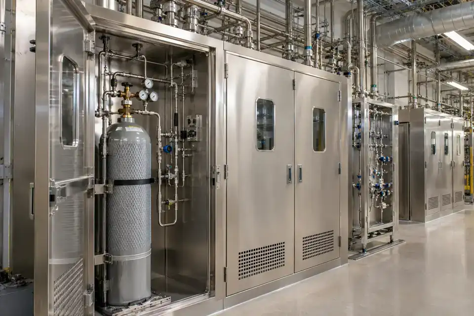
Sulfur-dioxide cylinder and transfer stations

SO2 concentration for the defined toxic-gas leak monitoring duty.
Industrial sulfur-dioxide transfer station with secured gas cylinders, a transfer manifold and organized service pipework
Sulfur-dioxide cylinder and transfer stations · Illustrative application image

Select a gas-specific SO2 channel for cylinder handling and transfer stations that use sulfur dioxide. The site review should identify connections, transfer steps and nearby occupied or enclosed spaces where a release could reach people. Define the toxic-gas concentration duty, expected interference and warning requirements, then match candidate points, external power and service access to the actual installation and ventilation.
Measurements to observe
SO2 concentration for the defined toxic-gas leak monitoring duty.
Monitoring point
Candidate points around assessed cylinder connections and transfer equipment release paths.
Placement & installation
Assess gas movement, ventilation and material conditions; provide calibration access and document external power routing and applicable installation requirements.
Project details
SO2 inventory, cylinder and transfer arrangement, occupied areas, humidity, corrosion, interference and alarm response.
Discuss this application

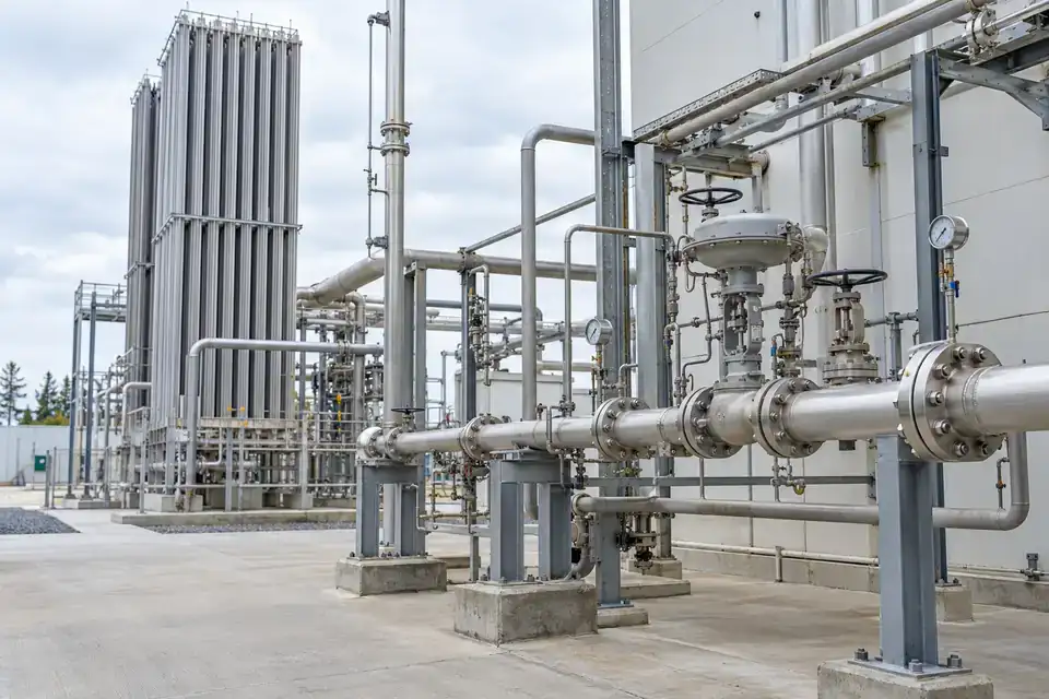
Semiconductor specialty-gas utility areas

H2 measurement for the specified combustible duty and NH3 toxic-gas measurement.
Semiconductor specialty-gas utility area with enclosed gas cabinets, organized stainless-steel pipework and clean service access
Semiconductor specialty-gas utility areas · Illustrative application image

Review H2 and NH3 channels for semiconductor utility areas where those gases are actually used. Hydrogen combustible-gas duties and ammonia toxic-gas duties need gas-matched measurement, with interference and operating conditions assessed separately. Define gas cabinets, manifold connections and ventilation paths, then confirm the monitoring points, ranges and required warnings with the supplied detector arrangement, external power and maintenance plan.
Measurements to observe
H2 measurement for the specified combustible duty and NH3 toxic-gas measurement.
Monitoring point
Candidate points around the identified gas cabinets, manifolds and utility release paths.
Placement & installation
Assess gas inventory, gas movement and ventilation; review sampling materials where relevant and confirm external power and approved installation conditions.
Project details
Actual specialty-gas inventory, cabinets and manifolds, airflow, H2 and NH3 ranges, interference and local warning requirements.
Discuss this application

Oxygen supply and enriched-atmosphere areas

O2 concentration for separately assessed enrichment and deficiency duties.
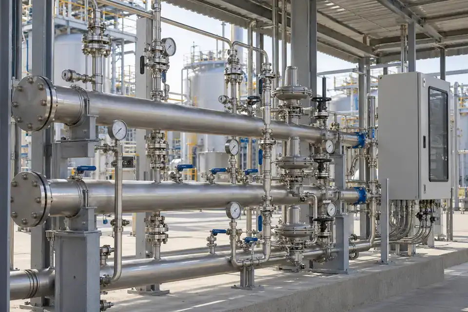
Industrial oxygen supply service area with an oxygen manifold, regulators, process pipework and a clear maintenance aisle
Oxygen supply and enriched-atmosphere areas · Illustrative application image

Define O2 monitoring around oxygen supply equipment and processes that can enrich the surrounding atmosphere. Oxygen supports combustion rather than acting as a combustible gas, so the measurement duty uses an oxygen-specific channel and appropriate high or low alarm requirements. Review leaks, ventilation and occupied locations, then select candidate monitoring points and the complete warning, power and service arrangement for the project.
Measurements to observe
O2 concentration for separately assessed enrichment and deficiency duties.
Monitoring point
Candidate points around assessed oxygen releases and relevant occupied or enclosed areas.
Placement & installation
Assess release conditions, gas movement and ventilation; confirm the oxygen channel and keep function testing, external power and service access practical.
Project details
Oxygen supply layout, credible releases, ventilation, occupied areas, high / low duty and required response.
Discuss this application

Chemical-plant gas manifolds

Site-selected CH4 combustible-gas, H2S toxic-gas and CO toxic-gas measurement duties.
Chemical plant gas manifold area with labeled process connections, valves, industrial pipework and accessible service routes
Chemical-plant gas manifolds · Illustrative application image

Build a monitoring arrangement around a chemical plant's actual manifold inventory, including CH4, H2S or CO where those gases are present. Combustible and toxic duties require separately selected gas-capable measurements and ranges. Review connections, process transfers, gas mixtures and occupied routes, then define candidate points, interference requirements and alarm behavior with the site's ventilation, external power and applicable hazardous-area installation conditions.

Measurements to observe
Site-selected CH4 combustible-gas, H2S toxic-gas and CO toxic-gas measurement duties.
Monitoring point
Candidate points around identified manifold connections and assessed transfer or ingress paths.
Placement & installation
Assess the actual mixture, gas movement and ventilation; maintain calibration access and document external power and the approved configuration's wiring requirements.
Project details
Manifold gas inventory, transfer sequence, mixed-gas interference, units and ranges, area classification, ventilation and alarm needs.
Discuss this application

SERIES & CONFIGURATIONS

One published family.
A gas configuration for your project.

H200, H300 and H500 are the published H Series custom-gas family. Define the gases, sensing duties, ranges, environmental conditions, mounting, external power, radio and alarm requirements together. Hitelecom confirms the model and channel arrangement for the project; the family gas list describes customization choices rather than a single terminal measuring every gas.

H Series custom gas sensors — project configuration reference
Published modelsH200 / H300 / H500
Customization scopeExamples: CH4 / H2 / NH3 / O2 / SF6 / CO2 / H2S / CO / SO2 and more; additional target gases configured per project
Target-gas arrangementSelected gas channels and terminal arrangement confirmed per project
Measuring range & unitsCustomized for the target gas and duty; ppm, vol% or %LEL as appropriate
Sensing principleGas-specific selection; published family lists electrochemical / NDIR / PID options
Accuracy & response timeConfirmed for the selected sensing channel, range and operating conditions
PowerExternal 9–24 V DC
InstallationFixed or ducted configuration; complete sampling arrangement reviewed where required
Wireless options4G LTE / NB-IoT / LoRa, by supplied variant and regional network support
Data protocol & platformMQTT listed; cellular reporting to Hitelecom Cloud or an agreed customer platform
Published cellular variant bandsLTE-TDD B34 / B38 / B39 / B40 / B41; LTE-FDD B1 / B3 / B5 / B8; regional compatibility confirmed for the project
ConfigurationPublished NFC activation and local setup
Enclosure protectionCustomizable enclosure; published IP68 option, with gas inlet and configuration conditions confirmed
Hazardous-area suitabilityApplicable detector approval, exact supplied configuration and installation conditions confirmed against the site classification
Alarm & control interfacesThreshold notifications and any required local warning / control interfaces defined and confirmed per project
Inspection & calibrationTarget-gas method, function testing, calibration and replacement plan defined for the selected sensor and site

Bring the specification back to your project.

01

Define the gas duty

Target gases · Units and ranges · Expected concentrations · Response time · Interfering gases

02

Define the installation

Release sources · Ventilation · Mounting · 9–24 V DC power · Area classification · Service access

03

Define the response path

Wireless variant · Receiving platform · Upload timing · Local alarm requirements · Control interfaces

CONNECTIVITY & INTEGRATION

Hitelecom Cloud.
Gas data for your workflow.

The published 4G and NB-IoT configuration reports via MQTT to Hitelecom Cloud or a customer platform. Agree the endpoint, authentication, payload and identifiers for the supplied terminal. For LoRa, confirm the radio protocol, gateway and server route. Dashboards and remote threshold notifications support operational review. Required local alarms, ventilation interfaces or shutdown functions need a defined control design and engineering confirmation for the complete system.

4G / NB-IoT

For distributed locations

Gas readingsMobile networkYour platform

Select the modem and regional bands around operator availability and coverage at the transmitter position. Agree the reporting profile, power arrangement and notification workflow.

  • Installation country and operator
  • Signal at the actual mounting position
  • Sampling, reporting and required alert response
LoRa

For points across one site

Gas pointsReceiver / gatewayYour platform

Match the supplied radio protocol, regional settings and receiver or gateway. Specify any LoRaWAN requirement with the model and complete onward connection.

  • Device protocol and gateway compatibility
  • Site layout and radio coverage
  • Gateway power and onward data connection

Make the first reading useful.

Agree device identity, monitoring-point reference, channel names, measurement units and timestamps in a sample message. Check the endpoint and supported authentication, then test the complete path to the intended platform and recipients.

Discuss platform integration ↗

ANSWERS FOR YOUR PROJECT

Frequently asked questions.

Practical answers for choosing target gases, configuring sensing and external power, assessing installation conditions and connecting data to the required site response.

Ask about your project ↗
Which gases can be configured?

Target gases include CH4, H2, NH3, O2, SF6, CO2, H2S, CO, SO2 and more. Share any additional target gases, expected concentrations and the purpose of the reading: combustible leak warning, toxic-gas monitoring, oxygen deficiency or enrichment, or an engineered process measurement. Hitelecom confirms the suitable sensing technology, selected channels, ranges and terminal arrangement in the proposal. Multi-gas projects are defined around the individual monitoring points and channel requirements.

Should our range use ppm, vol% or %LEL?

Choose the units for the gas and monitoring duty. Combustible leak warning commonly uses percentage of the lower explosive limit (%LEL), toxic-gas measurements commonly use ppm, and oxygen measurement uses vol%. Methane monitoring for low-level leak investigation differs from a %LEL warning duty. Share expected concentrations and required response so the configured range, resolution and alarm basis can be confirmed for each channel.

How is the sensing principle selected for H2, O2 and other gases?

Select the technology for the target gas and concentration duty. Conventional hydrocarbon infrared sensing does not detect hydrogen; hydrogen-capable catalytic and dedicated electrochemical approaches exist for different tasks. Oxygen needs an oxygen-specific channel, while PID detection depends on the gas and lamp and is commonly used for ionizable VOCs. Engineering reviews the exact sensor, interference, response and operating limits with the application.

Can a project monitor several gases?

Yes, a project can be specified with the gas inventory and monitoring points your team needs. Hitelecom confirms the available sensing channels and terminal arrangement for that request. Combustible, toxic and oxygen duties may require different channels or devices. Include likely gas mixtures and cross-sensitivity concerns so the selected measurements and their alarm requirements can be reviewed as a complete project.

How do we specify a configuration for a hazardous area?

Provide the site's hazardous-area classification and destination market with the enquiry. Match the supplied detector's applicable approval and exact configuration to the gas group, temperature and ambient conditions required at the site. Review the certificate coverage, marking, installation instructions and any conditions of use, including the power and wiring arrangement. Where IECEx documentation is applicable, verify the controlled online certificate and its current status.

How do enclosure protection and hazardous-area approval relate?

Select the enclosure and gas inlet for dust, water, corrosion and the required gas access. The published family describes a customizable IP68 option; confirm its test conditions for the supplied assembly. An ingress protection rating addresses dust and water. Hazardous-area selection separately requires the applicable detector approval, marking and installation conditions, and any required detection-performance or functional-safety evidence is assessed for the project duty.

What power supply should we plan?

The custom gas configuration uses external 9–24 V DC power. Include the available supply, cable route, isolation and service access in the project brief. Engineering confirms the supply requirements and wiring for the selected detector and installation, including the applicable hazardous-area conditions. Agree any continuity requirements together with the sensing, alarm and communication duties so the complete arrangement can be documented before commissioning.

How can we connect readings and remote notifications?

The published family lists 4G, NB-IoT and LoRa variants and MQTT. For a cellular project, confirm the modem, regional network support, endpoint, authentication and payload. For LoRa, agree the gateway and server route. Set upload timing and remote threshold notifications for the operating workflow, and confirm timestamps, communication-fault handling and any required local warnings separately with the supplied configuration.

Can the system support ventilation or shutdown requirements?

Include the required protective action in the enquiry so the interfaces and complete control design can be reviewed. Define the local detection and warning path, response time, fault behavior and test requirements. A remote threshold notification is an operational data function; a ventilation or shutdown duty needs the appropriate controller path and approval evidence. Hitelecom confirms the available interfaces and project suitability before those functions are specified.

Where should gas-monitoring points be placed?

Choose candidate points from probable releases, gas dispersion, ventilation, obstructions and exposure locations. Gas density is one input: release temperature, gas mixtures and circulation can change the path, so a universal ceiling or floor height is unsuitable. Review the layout against the selected detector documentation and site assessment, with practical access for calibration and replacement. Where needed, use dispersion analysis or airflow checks to refine the plan.

When is fixed, ducted or sampled monitoring appropriate?

Match the arrangement to the release source and measurement purpose. A fixed point measures gas reaching that point; a duct sample represents the sampled stream. Where tubing is used, review gas and material compatibility, adsorption, condensation, filters, flow faults and transport delay. Select and verify the complete gas path with the detector so its measurements represent the intended location and required response.

What information helps prepare the quotation and service plan?

Provide target gases, units and ranges, point count, process and ambient conditions, area classification, external power, communication and alarm requirements. Add a site layout and likely interfering gases. Request the final channel specifications and applicable approvals, plus the calibration method, function-test schedule and replacement plan. Inspection and maintenance intervals are selected for the actual sensor and site conditions, with commissioning checks for the complete measurement and response path.

LET'S TALK ABOUT YOUR PROJECT

Tell us about the gas.
Build the monitoring configuration.

Share the gases, industrial setting and the measurement or response your team needs. Hitelecom can review the sensing channels, ranges, enclosure, mounting, external power and wireless arrangement, then prepare a quotation around the project conditions.

sales@hitelecom.cn ↗

Your gases. Your project requirements.

A site layout helps define release sources, candidate points and service access. Include gases, concentrations, ventilation, ambient conditions, area classification, 9–24 V DC supply and data or alarm requirements where available.

PROJECT ENQUIRY

Let’s define your gas configuration.

Start with your application. Add the details you already know.

Your proposal will identify the selected gas channels and terminal arrangement.

Range, site protection & data requirements

Review your brief, then send it with your email app.

You can also email your project details directly.