


SPD condition monitoring
Monitor the operating condition of surge protective devices. Identify SPDs requiring attention so inspection and replacement can be based on the condition of the monitored protection equipment.

HiSPD-DPU-04 is an intelligent monitoring terminal for surge protective devices (SPDs). Four simultaneous monitoring channels provide condition information to help electrical maintenance teams identify SPDs requiring inspection or replacement. Applications include selected protection points in building electrical services, wind-energy auxiliaries and field equipment. The series offers 2-, 4- and 8-channel configurations.
MONITORING & MAINTENANCE
Four simultaneous channels provide SPD condition information for inspection and replacement decisions. Apply the terminal to selected protection points in building services and electrical equipment.
Monitor the operating condition of surge protective devices. Identify SPDs requiring attention so inspection and replacement can be based on the condition of the monitored protection equipment.
HiSPD-DPU-04 brings four SPD monitoring channels into one terminal. Monitor the selected protection points together within the agreed installation arrangement.
Use SPD condition information to determine which protection device needs inspection or replacement. Direct maintenance to the indicated device within the electrical installation.
Select the series variant for the required number of monitoring channels. HiSPD-DPU-04 is the four-channel model shown on this page.
Apply SPD monitoring at selected protection points in main distribution, local boards and rooftop-services cabinets. Include SPD condition in the building’s electrical maintenance programme.
Extend the monitoring plan to selected SPDs in wind-energy auxiliary systems and field cabinets. Specify the protection devices and cabinet conditions for the installation.
SPD CONDITION & MAINTENANCE
An SPD limits transient overvoltages within an electrical installation. Protected equipment may continue operating even when its SPD requires maintenance. Monitoring the protective device provides a separate basis for assessing that service need. HiSPD-DPU-04 monitors four SPD channels simultaneously, helping the electrical maintenance team identify the protection point concerned and arrange inspection or replacement.
Find your applicationObtain condition information from the SPDs included in the four-channel monitoring arrangement.
Use the channel assignment to identify the relevant SPD and the distribution board or equipment it serves.
Assess the indicated device and follow the SPD manufacturer’s inspection and replacement instructions.
FROM SPD CONDITION TO MAINTENANCE
Connect the monitoring indication to the assigned SPD, assess the service requirement and carry out the appropriate maintenance. A documented channel assignment makes the relevant protection point identifiable.
Monitor four SPD channels simultaneously with HiSPD-DPU-04.
Relate the indicated channel to the assigned SPD and protection point.
Review the condition indication and assess the device under the applicable service procedure.
Replace the SPD where indicated and verify completion of the maintenance work.
Assess condition indications using the SPD manufacturer’s service instructions and the installation’s electrical maintenance procedure. Inspection and replacement are performed by the responsible maintenance team.
APPLICATIONS
Monitor the condition of selected SPDs protecting electrical distribution and equipment interfaces. Applications include building distribution, rooftop services, wind-energy auxiliaries and distributed electrical infrastructure. Define the monitored SPDs and a compatible monitoring arrangement for each installation.
11 industry categories 44 monitoring applications
Application illustrations show representative environments, not customer installation records.
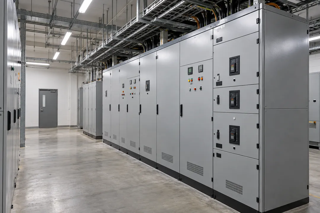
Monitor selected SPDs in building distribution and services, from incoming boards to rooftop equipment. Condition information helps the facilities team identify protective devices requiring inspection or replacement at the relevant electrical protection point.
Monitor the SPDs installed at the building’s incoming distribution board. Condition information helps the facilities team identify a protective device requiring attention at this central electrical protection point. Relate the indication to the relevant board and arrange inspection or replacement through the building’s maintenance process.
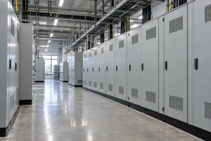
Monitor selected SPDs in floor and tenant distribution boards. Where a building contains many similar panels, the monitoring indication needs a clear board identity to direct maintenance to the correct device. Coordinate the resulting SPD inspection or replacement with the affected building-service area.
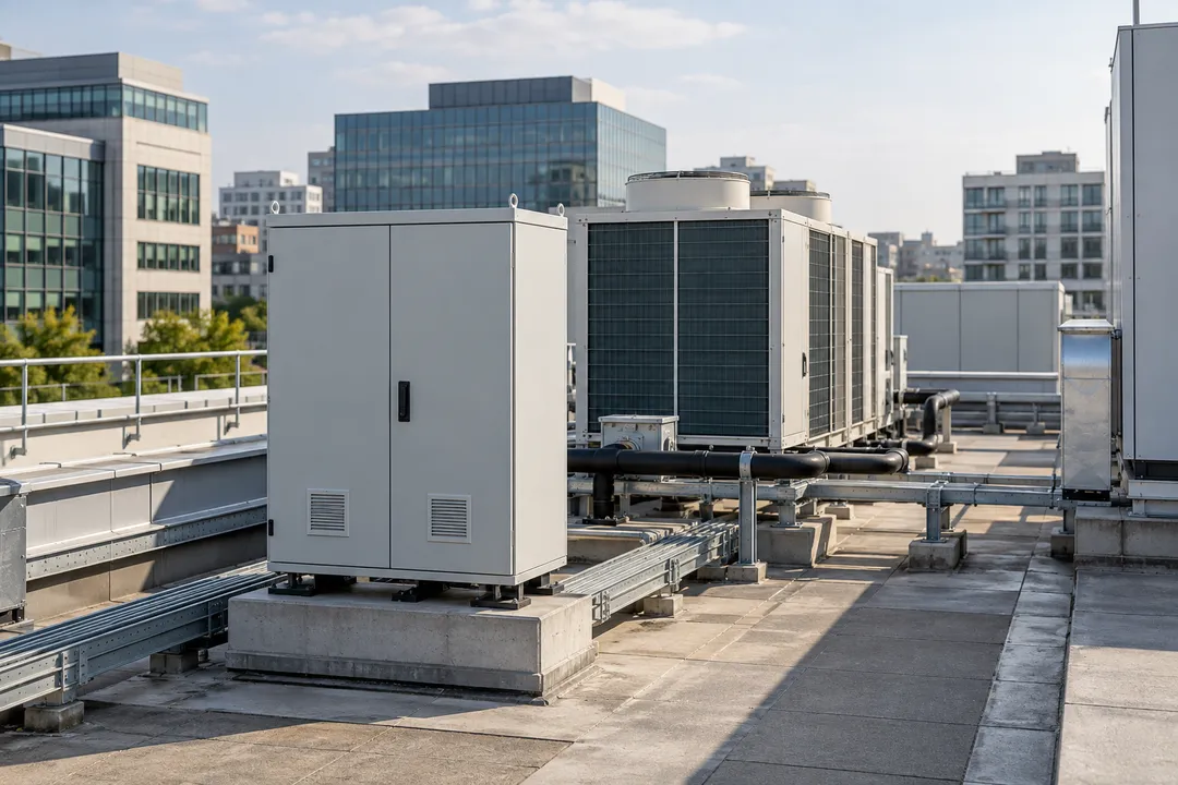
Monitor selected SPDs serving rooftop plant and auxiliary cabinets. These protection points belong to a building service even when the equipment is physically separated from the main electrical rooms. Condition information supports attention to the relevant SPD within the rooftop equipment’s maintenance routine.
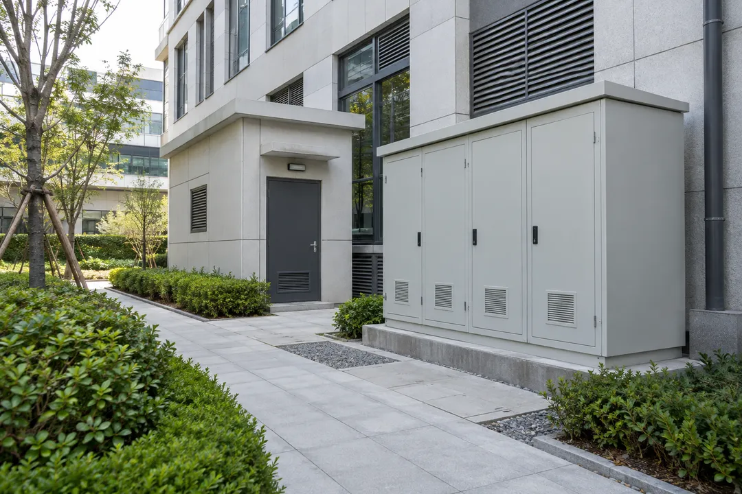
For a compatible protection arrangement, monitor selected SPDs at building IT and security interfaces. Keep the protective device distinct from the connected network or security equipment. An SPD condition indication helps identify the protection-maintenance task and assign it to the relevant service team.
Bring SPD condition monitoring into the electrical maintenance of public and occupied buildings. Locate the monitored protection points within each facility so maintenance attention can be directed to the appropriate distribution or building-service equipment.
Monitor selected SPDs in hospital electrical distribution and building-service panels. Condition information helps the facilities team recognize a protection-device service need at a defined panel. Plan the resulting inspection or replacement within the hospital’s electrical maintenance procedures and the operating requirements of occupied facilities.
Monitor selected SPDs across campus distribution and building-service cabinets. Grouping protection points by building helps separate similar electrical equipment across teaching, residential and administration areas. Use the condition indication to direct maintenance attention to the relevant SPD and the team responsible for that property.
Include selected civic-building SPDs in the property’s electrical monitoring plan. Condition information can identify a protective device needing attention without treating every distribution board as one maintenance location. Link the SPD service task to the correct property, panel and facilities responsibility.
Monitor selected SPDs serving terminal-building electrical distribution and auxiliaries. Stations and airports contain repeated panels across separate service zones, making the protection-point identity important when reviewing a maintenance indication. Coordinate SPD inspection or replacement with the terminal’s established building electrical maintenance arrangements.
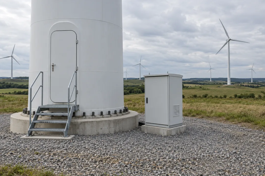
Monitor selected SPDs serving wind-turbine auxiliaries and wind-farm field equipment. Distinguish tower-base, nacelle, transformer auxiliary and SCADA protection points so condition information can support maintenance at the correct part of the installation.
Monitor selected SPDs in wind-turbine tower-base auxiliary and control cabinets. Relate the condition indication to the turbine and cabinet so the service team can identify the protective device concerned. Include the resulting inspection or replacement in the maintenance work for that turbine.

For the selected protection arrangement, monitor SPDs serving nacelle auxiliary and control equipment. A condition indication tied to the turbine and protected service helps define the SPD maintenance task before nacelle work is planned. Coordinate inspection or replacement within the operator’s turbine service procedures.
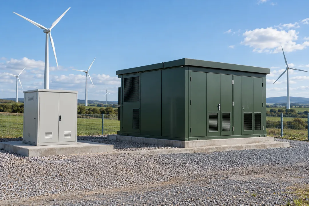
Monitor selected SPDs in the low-voltage auxiliary and control services of wind-farm transformer stations. These protection points serve the station’s auxiliary equipment rather than its primary power circuit. Condition information helps the electrical team identify the relevant SPD for inspection or replacement.
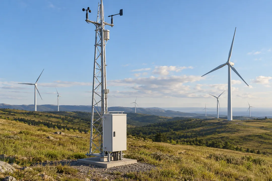
Monitor selected compatible SPDs at wind-measurement and SCADA field cabinets. Identify the protection point by mast or outstation and the service it protects. A condition indication supports SPD maintenance at scattered field locations while remaining distinct from instrument measurement or communications diagnostics.

Monitor selected SPDs within data-center electrical distribution and compatible interface-protection arrangements. Keep each protection point distinct from the UPS, server or network equipment it serves, with condition information supporting the SPD maintenance task.
Monitor selected SPDs at data-center incoming distribution boards. Keep the monitoring point associated with the facility’s supply-path and board identity so a protection-device indication is reviewed at the correct location. Plan the resulting SPD inspection or replacement within the established electrical maintenance process.
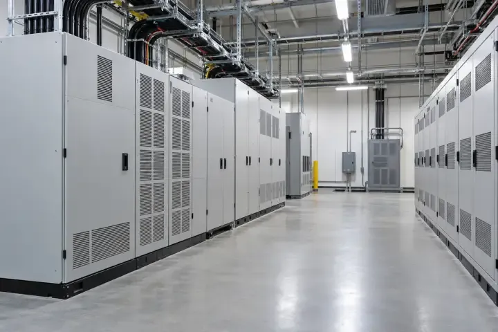
Monitor selected SPDs in UPS-related and downstream distribution boards. The monitoring focus is the protective device at the electrical protection point, with its own condition and service requirement. Relate any indicated maintenance need to the correct board before arranging SPD inspection or replacement.
For compatible monitored devices, include SPDs protecting external metallic-signal entries. Associate the condition indication with the interface and protection location so network and facilities teams can identify the SPD concerned. This defines the protective-device service task separately from maintenance of the connected IT equipment.
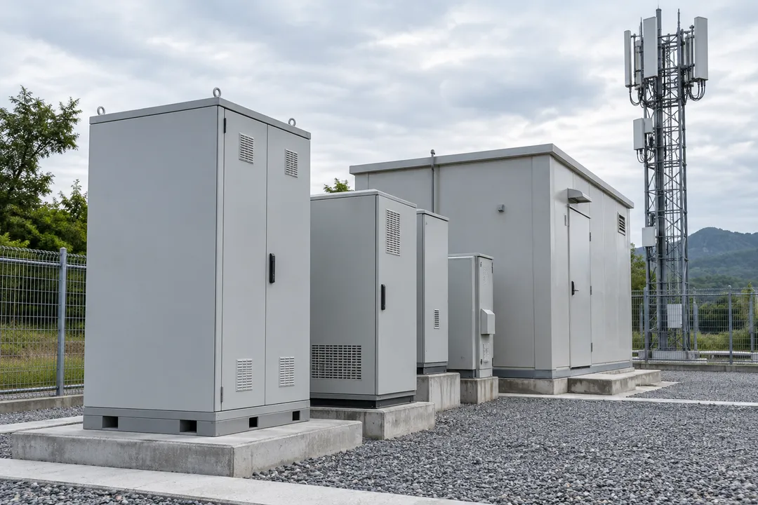
Monitor selected SPDs in edge-site power and auxiliary cabinets. A protection-device indication needs a defined site and cabinet identity where several small installations use similar equipment. The maintenance team can then identify the relevant SPD and include its inspection or replacement in the site service work.
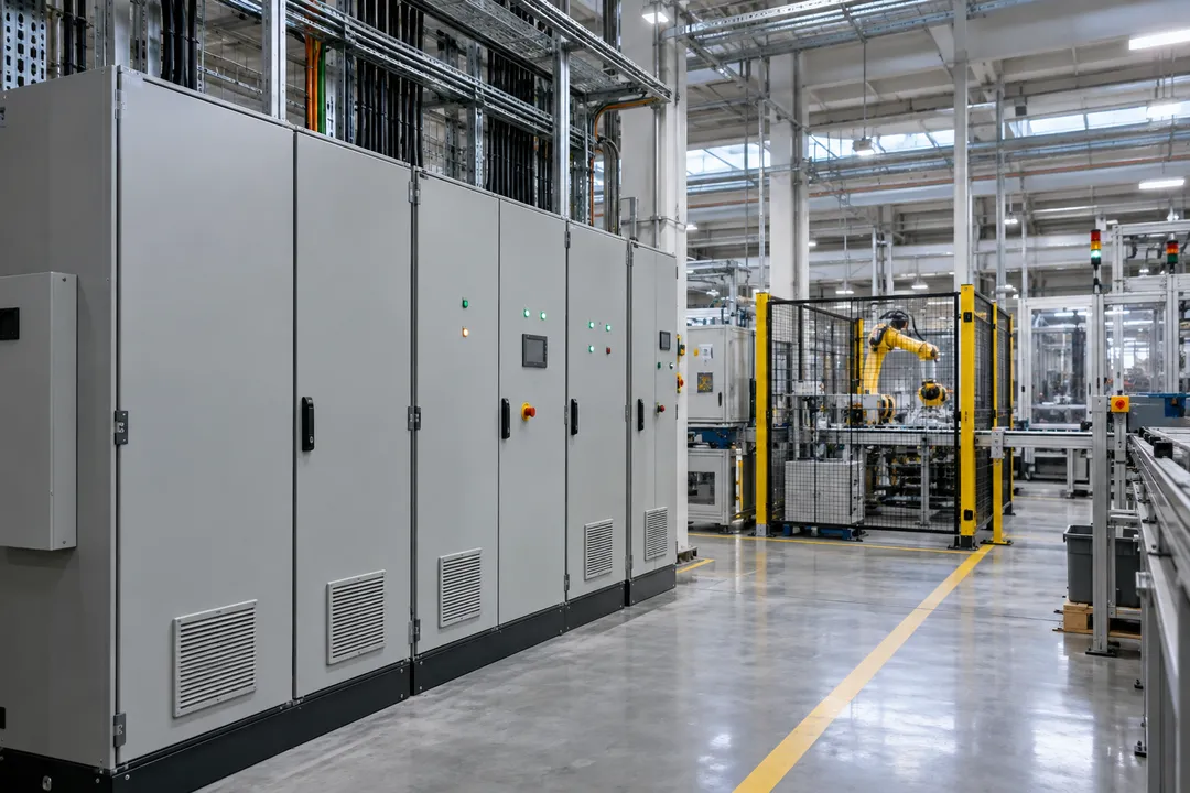
Include SPD condition in the maintenance of production, instrumentation and warehouse electrical equipment. Identify the protective devices serving each panel or equipment group so an indicated service need reaches the relevant electrical or automation team.
Monitor selected SPDs in production-cell power and auxiliary panels. Relate the condition indication to the line, panel and protected service so the electrical team can identify the device needing attention. Coordinate SPD inspection or replacement with the maintenance requirements of the relevant production equipment.
For a compatible arrangement, monitor selected SPDs serving process instrumentation. Keep the protection point linked to its cabinet and protected interface so a condition indication reaches the relevant electrical or instrumentation team. Review the SPD service need separately from the condition of the process instrument.
Monitor selected SPDs in warehouse electrical distribution boards. Large facilities may have similar panels across separate storage and operating zones, so the relevant board identity helps direct attention to the correct protective device. Include the indicated SPD inspection or replacement in the facility’s electrical maintenance routine.
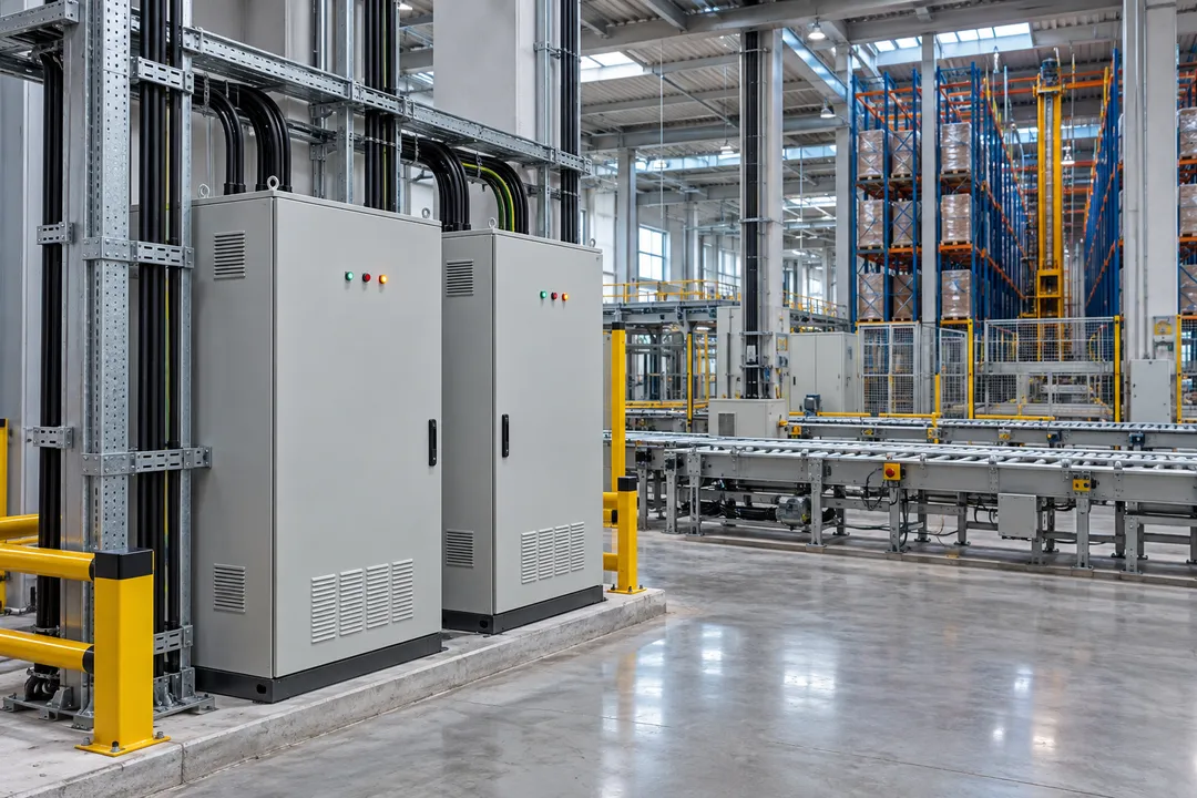
Monitor selected SPDs in automated storage and conveyor control cabinets. Identify the protected service and equipment zone when reviewing a condition indication, helping the electrical or automation team establish the SPD service task. Coordinate inspection or replacement with maintenance of the associated warehouse equipment.
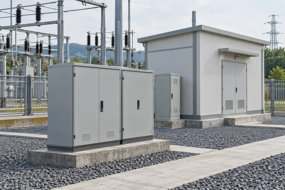
Apply SPD condition monitoring to selected utility auxiliary, control and communications protection points. Each monitored device should remain associated with its station and cabinet, within the proposed SPD connection arrangement.
Monitor selected SPDs in secondary-substation auxiliary and control panels. Associate the indication with the station and protection point so the utility team can identify the device requiring attention. Keep the SPD task within the station’s defined equipment boundaries and electrical maintenance arrangements.
For compatible protection arrangements, monitor selected SPDs in utility telecontrol cabinets. These points may serve auxiliary supplies or metallic interfaces associated with the outstation. A clear condition indication helps identify the relevant SPD maintenance task without treating it as a diagnosis of the RTU or communications equipment.
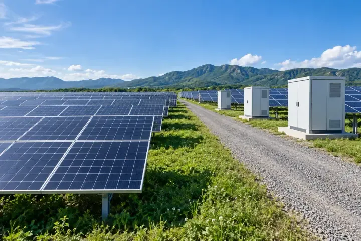
Monitor selected SPDs at low-voltage distributed-energy connection boards. Relate the condition indication to the site, board and protective device so maintenance attention reaches the correct electrical protection point. Define service responsibility where the generator owner, network operator and electrical contractor maintain different parts of the installation.
Monitor selected compatible SPDs in remote switching-site communications or auxiliary cabinets. Associate each point with its cabinet and protected service so the field team can identify the device needing attention. Keep the SPD service task within the site owner’s equipment and electrical maintenance boundaries.
Monitor selected SPDs within compatible solar and energy-storage protection arrangements. Separate DC, AC and auxiliary protection points when selecting the monitoring connection and planning the maintenance response for each installation.
Subject to confirmation of the SPD monitoring connection, include selected SPDs in PV combiner boxes. Identify the array area and box when reviewing a condition indication across repeated field enclosures. This directs maintenance attention to the relevant protective device and its specific DC protection arrangement.
Monitor selected SPDs in inverter-station AC distribution boards. Relate the indication to the station and board so the electrical team can identify the correct protection point among repeated inverter groups. Include the resulting SPD inspection or replacement within the plant’s electrical maintenance process.
Monitor selected SPDs serving solar-site auxiliary and control equipment. Keep these protection points distinct from combiner-box DC and inverter AC protection when reviewing a condition indication. This helps identify the relevant SPD and direct maintenance to the team responsible for the site-service cabinet.
For the selected compatible arrangement, monitor SPDs serving energy-storage auxiliary or communications equipment. Identify the container, service cabinet and protection point so an indication reaches the relevant maintenance team. Review the SPD service requirement within the equipment supplier’s installation and maintenance arrangements.
Monitor selected SPDs serving radio-site power, auxiliary equipment and compatible metallic interfaces. Associate each protection point with the site and equipment service it supports, helping field teams direct maintenance to the relevant protective device.
Monitor selected SPDs in mobile-base-station power and auxiliary cabinets. Keep the protection point associated with the radio-site and cabinet identity so the field team can identify the device requiring attention. Include SPD inspection or replacement within maintenance of the relevant site-service equipment.
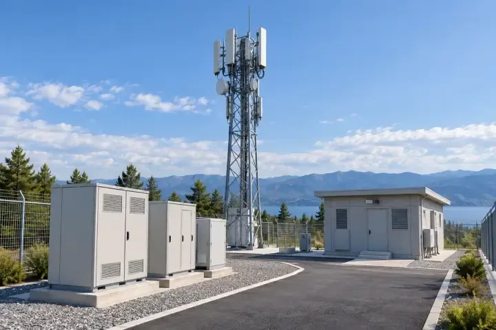
Monitor selected SPDs serving rooftop radio equipment rooms and auxiliary cabinets. A condition indication should identify the protection point within the property and radio installation, helping telecommunications and building teams assign the SPD maintenance task. Coordinate inspection or replacement with the relevant equipment service responsibility.
For compatible monitored devices, include SPDs serving remote network-access cabinets. Relate the indication to the site, cabinet and protected interface so the field team can identify the relevant protection device. Keep its inspection or replacement distinct from fault investigation of the connected network equipment.
Monitor selected compatible SPDs in broadcast and repeater-site auxiliary equipment. Identify the station and protection point when reviewing the condition indication, particularly where several remote sites use similar cabinets. This helps the service team define the SPD inspection or replacement task for the relevant installation.
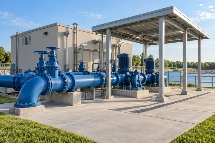
Monitor selected SPDs in water-site power and control equipment. Identify protection points at pumping stations, wells, treatment cabinets and remote outstations so condition information can support maintenance across the water network.
Monitor selected SPDs in pumping-station electrical and control cabinets. Relate the condition indication to the station, panel and protected service so the maintenance team can identify the device requiring attention. Include the resulting SPD service task within the station’s electrical equipment maintenance programme.
Monitor selected SPDs serving groundwater-well control equipment. Associate the indication with the well and cabinet to distinguish similar protection points across the network. This helps the field team identify the relevant device and include its inspection or replacement in maintenance of the well-control installation.

For compatible protection arrangements, monitor selected SPDs serving water-treatment instrumentation. Identify the process area, cabinet and protected interface when reviewing a condition indication. The electrical or instrumentation team can then define the protective-device service task separately from maintenance of the instrument or treatment process.
Monitor selected compatible SPDs in remote water-control outstations. Keep each protection point linked to its station and protected service, helping the maintenance team distinguish similar field cabinets. A condition indication can then support inspection or replacement of the relevant SPD within the water network’s service programme.
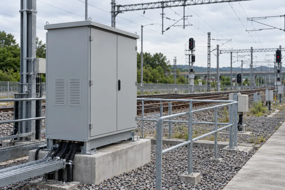
Monitor selected SPDs at transport infrastructure cabinets within the equipment owner’s accepted arrangement. Relate condition information to a specific protection point and coordinate the resulting service task through the responsible maintenance organization.
For an owner-accepted monitoring arrangement, include selected SPDs in railway signaling cabinets. Relate the condition indication to the specific cabinet and protection point so the infrastructure team can identify the SPD concerned. Coordinate inspection or replacement through the owner’s equipment assessment and maintenance procedures.
Monitor selected compatible SPDs in level-crossing auxiliary and interface cabinets within the infrastructure owner’s accepted arrangement. Identify the crossing and protection point when reviewing an indication. This supports a defined SPD maintenance task, coordinated through the responsible railway equipment and electrical maintenance teams.
Monitor selected compatible SPDs in road and tunnel control panels. Identify the tunnel zone, service panel and protected interface when reviewing the condition indication. This helps the maintenance team locate the relevant protective device and coordinate its inspection or replacement within tunnel-services electrical maintenance.
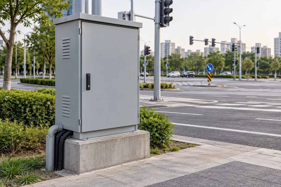
Monitor selected compatible SPDs serving roadside traffic cabinets. Relate the condition indication to the junction, cabinet and protected service so maintenance attention reaches the relevant protective device. Coordinate SPD inspection or replacement through the road operator’s electrical and roadside equipment maintenance arrangements.

Monitor selected SPDs in charging infrastructure and municipal electrical distribution. Keep feeder, board and cabinet protection points distinct so maintenance attention can be directed to the relevant device and equipment operator.
Monitor selected SPDs in fleet and workplace AC charging-area distribution boards. Keep the indication associated with the charging zone and board so the facilities team can identify the relevant protective device. Coordinate its inspection or replacement with maintenance of the charging-area electrical distribution.
For a compatible charging-site arrangement, monitor selected SPDs at public DC charging installations. Relate the indication to the station, cabinet and actual protection point so the service contractor can identify the SPD concerned. Match the monitoring connection to the installed protective device and electrical arrangement.
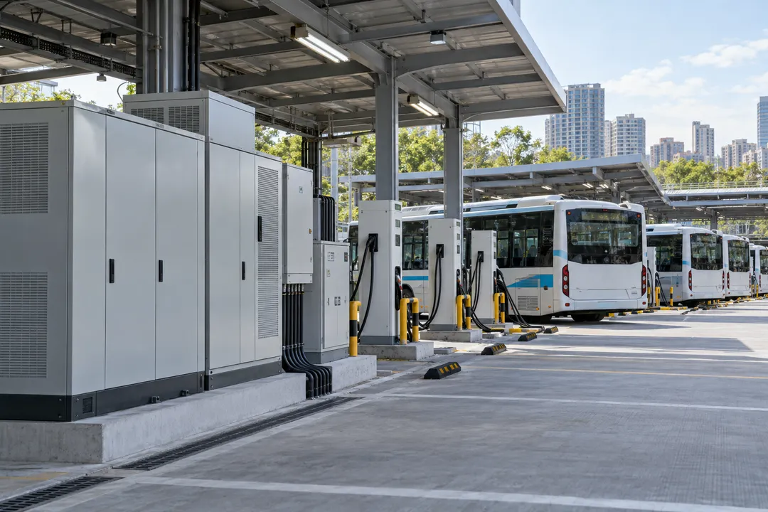
Monitor selected SPDs in bus-depot charging distribution and auxiliary panels. Identify the feeder, bay or service panel when reviewing an indication across repeated charging equipment. This helps the electrical team direct SPD maintenance to the relevant protection point within the depot’s charging installation.
Monitor selected SPDs in street-lighting feeder and service cabinets. Relate each condition indication to its district, feeder and cabinet so the municipal maintenance team can identify the relevant protective device among similar installations. Include the SPD inspection or replacement in the electrical service task for that feeder.
MODEL & CHANNEL OPTIONS
HiSPD-DPU-04 is the four-channel intelligent SPD monitoring terminal. The series also offers 2- and 8-channel versions. Select the required channel count and confirm the monitoring arrangement for the installed SPDs.
Four simultaneous SPD monitoring channels, with condition information to support inspection, maintenance and replacement of the monitored protection devices.
Download the HiSPD-DPU-04 datasheet (PDF) Discuss the channel options ↓| Model | HiSPD-DPU-04 |
|---|---|
| Simultaneous monitoring | 4 SPD channels |
| Monitored equipment | Surge protective devices (SPDs) |
| Monitoring function | SPD condition monitoring |
| Maintenance support | Maintenance and replacement indication |
| Series channel options | 2-channel, 4-channel and 8-channel versions |
Channel count refers to monitoring channels. Confirm SPD compatibility, channel assignment and wiring using the technical documentation for the selected version.
Match the terminal to the SPDs, monitoring connections and installation conditions.
Define the required monitoring points and channel assignment. Choose a 2-, 4- or 8-channel series variant; HiSPD-DPU-04 provides four simultaneous channels.
Identify the SPD manufacturer, model and proposed monitoring connection. Review these against the terminal’s supported arrangement before finalizing the selection.
Provide the cabinet drawing, available supply, mounting space and environmental conditions. Confirm the electrical and installation requirements for the chosen version.
Specify the condition information required by the receiving system and the intended maintenance response. Confirm the supported interface and information mapping for the supplied terminal.
INSTALLATION & SYSTEM INTEGRATION
An effective monitoring arrangement identifies the SPD, the monitoring channel and the information needed for maintenance. Confirm the device connections and supported terminal interface for the selected configuration.
Define which SPDs are included, how their monitoring connections are assigned and which protection point each channel represents. Use the SPD and terminal documentation to establish the installation arrangement.
Specify how the receiving system will use SPD condition information. Agree the supported communication interface, information definitions and equipment references before implementation, so the maintenance team can act on the correct protection device.
Use the same channel, SPD and cabinet references in the installation drawings and receiving-system configuration. This links a condition indication to the protection point requiring inspection or replacement.
Discuss system integration ↗SPD MONITORING: TECHNICAL QUESTIONS
Direct answers about SPD condition monitoring, four-channel operation, compatibility, installation and maintenance.
Ask about your project ↗HiSPD-DPU-04 is an intelligent terminal for monitoring the operating condition of surge protective devices (SPDs). It monitors four channels simultaneously and provides condition information to support inspection and replacement decisions.
The series includes 2-, 4- and 8-channel configurations. HiSPD-DPU-04 identifies the four-channel model.
Understand SPD monitoring →A surge protective device limits transient overvoltages in an electrical installation. SPDs are used at defined protection points in electrical distribution and equipment interfaces.
The SPD performs the protective function. The monitoring terminal provides information about the condition of the selected protective devices.
Review the monitoring role →SPD condition monitoring helps electrical maintenance teams identify protective devices requiring inspection or replacement. It adds information about the protective device itself to the maintenance decision.
HiSPD-DPU-04 provides this information through four simultaneous monitoring channels. Each channel must have a defined assignment within the selected SPD monitoring arrangement.
See the maintenance workflow →Equipment operation alone does not establish the condition of its surge protection. An SPD can require maintenance while the associated equipment continues operating.
Monitoring the SPD gives the maintenance team a separate basis for reviewing the protective device and arranging inspection or replacement where indicated.
Connect monitoring to maintenance →An existing installation can be assessed for a supported SPD monitoring arrangement. Compatibility depends on the SPD model, its monitoring connection and the terminal configuration.
Provide the SPD manufacturer and model, connection details and cabinet drawing. Confirm compatibility against the selected terminal’s technical documentation before installation.
Discuss an existing installation →Yes. HiSPD-DPU-04 monitors four SPD channels simultaneously. The series also offers 2- and 8-channel versions.
A monitoring channel is not a phase or pole count. Its relationship to SPD modules or protection modes is defined by the documented connection arrangement.
Review the channel options →SPD condition monitoring and surge-current measurement address different information needs. The former concerns the protective device’s condition; the latter measures an electrical event using a specified sensing arrangement.
If event measurement is required, specify it separately and confirm the supporting equipment and configuration. It should not be inferred from the SPD monitoring product category.
Describe your monitoring requirements →Condition information helps identify which monitored SPD needs assessment and defines the protection point involved. The maintenance team can use that information to determine the required inspection or replacement work.
The service decision follows the SPD manufacturer’s instructions and the site’s maintenance procedure. Monitoring information supports that decision; it does not perform the maintenance.
Explore the monitoring locations →The installation design assigns each monitoring channel to a specified SPD monitoring point. Record that assignment with the board, cabinet and equipment references in the electrical drawing.
Use the same identifiers in the receiving system where applicable. This allows the team to relate an indication to the intended protection device.
Review the monitoring arrangement →Check the selected SPD monitoring connection, terminal supply requirements, mounting arrangement, wiring access and cabinet environment against the documentation for the supplied version.
For rooftop and outdoor equipment, include the enclosure conditions in the review. Obtain the matching electrical and installation information before finalizing the design.
Share the installation details →Define the SPD condition information the receiving system needs, together with the channel and equipment identifiers used by the maintenance team.
Match those requirements to the supported interface, communication specification and information format of the supplied terminal version. Confirm the configuration before implementing the integration.
Review integration requirements →Review an indicated maintenance need against the SPD manufacturer’s service instructions and the site’s electrical maintenance procedure. The responsible team determines whether inspection, replacement or another specified service action is required.
Use the channel assignment to identify the correct device and verify completion of the required work.
Follow the service workflow →Typical candidate locations include main distribution boards, floor and tenant boards, rooftop-services cabinets and compatible IT or security protection interfaces.
Select the monitored points around the installed SPD models and supported connections. The required monitoring-channel count determines the appropriate series configuration.
Explore building applications →Candidate points include SPDs in turbine tower-base cabinets, nacelle auxiliary systems, transformer-station low-voltage auxiliaries and measurement or SCADA field cabinets.
Confirm the SPD connection and terminal installation requirements for each selected point. The monitoring task concerns the SPD, rather than wind measurement or diagnosis of the protected equipment.
Explore wind-energy applications →SPD condition monitoring supports inspection and replacement decisions. The SPD manufacturer’s instructions and the site’s maintenance procedure still define the required service work.
Use the monitoring indication to direct attention to the relevant device, assess its service requirement and verify that the required maintenance has been completed.
Discuss the maintenance process →DISCUSS YOUR SPD MONITORING APPLICATION
Share the SPD manufacturer and model, required monitoring channels and installation drawing. Include cabinet conditions and any receiving-system requirements. We can review the appropriate series version and technical information for your application.
sales@hitelecom.cn ↗Provide the SPD models, monitoring arrangement, channel count and installation conditions so the terminal selection can be reviewed against your requirements.