


Industrial Ethernet switches.Connect the equipment.
Build the site network.

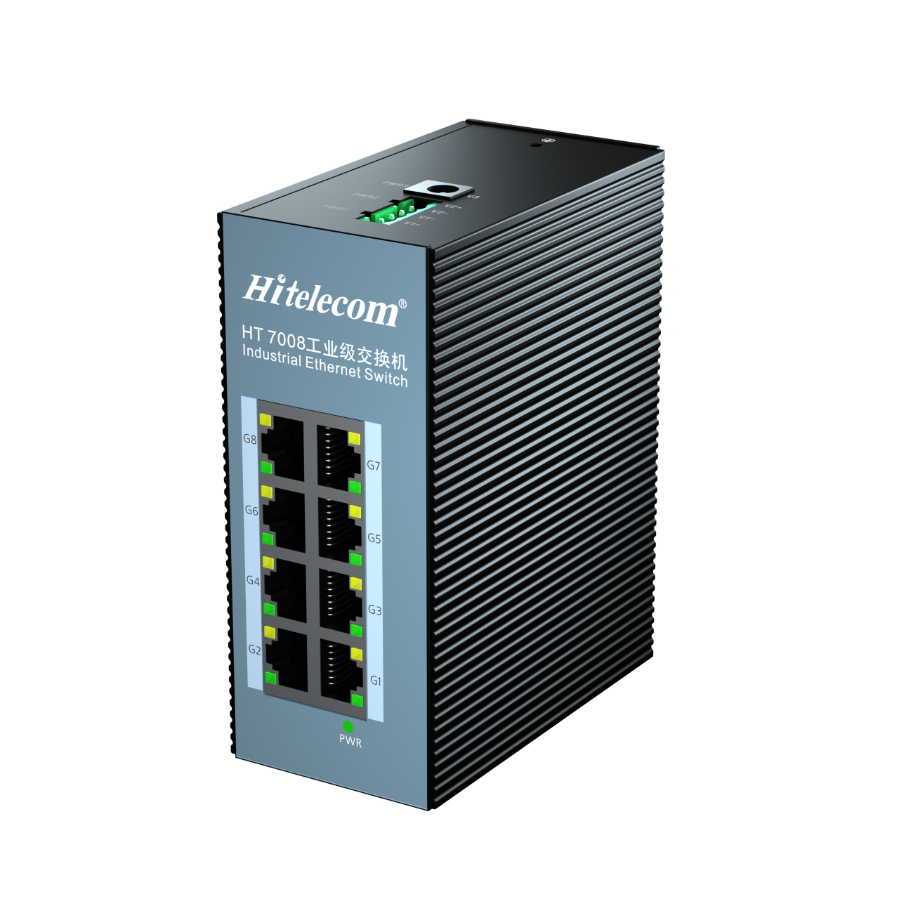
Original Hitelecom HT7008 industrial Ethernet switch with eight RJ45 ports and a finned aluminium-alloy enclosure
HT7000 Series · HT7008 reference

The Hitelecom HT7000 series brings Gigabit Ethernet connectivity to industrial equipment networks. The pictured HT7008 provides eight RJ45 ports with 10/100/1000 Mbps auto-negotiation, an aluminium-alloy enclosure and an operating temperature range of -40 to +75 °C. Develop the project configuration around the connected devices, cabinet power, installation environment and network requirements.

8 × GigabitHT7008 copper-port referenceAllocate equipment and upstream links within eight ports
-40 to +75 °CIndustrial operating rangeReview the actual cabinet conditions
Custom configurationDefined around your projectAgree hardware, network scope and verification

KEY FEATURES

Industrial connectivity.
Defined for the installation.

Start with the eight-port Gigabit reference, then align Ethernet links, DC supply, enclosure conditions and the agreed customization scope.

Eight-port Gigabit reference

The illustrated HT7008 provides eight copper Ethernet ports. Build the port schedule around connected equipment, the upstream connection and any required spare capacity.

10/100/1000 Mbps auto-negotiation

Connect compatible Ethernet devices operating at the supported link speeds. Verify the negotiated rate and end-to-end application traffic during commissioning.

Aluminium-alloy enclosure

The metal enclosure and external fins provide a practical mechanical format for industrial cabinets. Define mounting, access and thermal clearances for the installation.

Industrial operating temperature

The HT7008 reference operates from -40 to +75 °C. Assess the local cabinet temperature, heat sources and cooling as part of the installation design.

DC supply configuration

The reference lists 12, 24 and 48 V DC nominal supply values. Specify the input arrangement, allowable voltage tolerance and power-source requirements for the delivered version.

IEEE 802.3x flow control

The reference lists IEEE 802.3x flow control. Evaluate its behaviour with the connected devices and traffic profile; link-level flow control does not define application latency.

Local status visibility

The product illustration includes a power indicator and port-side indicators. Use the supplied indicator definitions together with endpoint checks to verify connection and operating status.

A documented custom configuration

Review port allocation, power, enclosure, network-function requirements and product identification with Hitelecom. Record the agreed design, acceptance criteria and delivery documents before production.

CONNECTIONS & INSTALLATION

Plan the links.
Coordinate the cabinet.

A clear port schedule, documented supply arrangement and reviewed installation conditions turn a product reference into a specified equipment-network node.

8 × RJ45

Copper Ethernet connections

Allocate the eight HT7008 ports between equipment connections and any upstream network link. Connect compatible Ethernet endpoints and confirm the negotiated speed of each link.

  • PLC, HMI and industrial computer connections
  • Camera, recorder and equipment-network links
  • An upstream connection within the same eight-port total
12 / 24 / 48 V DC

Cabinet power coordination

Use the listed nominal DC supply values as project-selection inputs. Confirm the permitted input range, terminal assignment, source arrangement and protective measures in the supplied electrical documentation.

  • Site supply and power-budget review
  • Input wiring, earthing and source allocation
  • Documented power-interruption and restoration checks
-40 to +75 °C

Enclosure and installation

Review the switch operating range against the actual cabinet conditions. Allow for nearby heat sources, enclosure cooling, cable access and the installation method defined for the ordered configuration.

  • Aluminium-alloy enclosure with external cooling fins
  • Cabinet access and cable-routing review
  • Environment and project-specific qualification review

FROM REQUIREMENTS TO HANDOVER

Specify. Validate.
Deliver a documented network.

Define the network requirement, approve the configuration and verify it with the actual equipment and installation conditions.

01

Define the network task

List the Ethernet endpoints, their traffic and the upstream connection. Record available ports, growth allowance, installation location and the project network boundary.

02

Specify the configuration

Agree the port schedule, DC supply arrangement, mechanical requirements and any requested network functions. Put approved customization and verification scope into the project specification.

03

Validate the agreed design

Evaluate the agreed sample or configuration with representative equipment and traffic. Verify link negotiation, supply behaviour, cabinet conditions and required recovery procedures against the acceptance criteria.

04

Document the delivered network

Hand over the port map, power and mounting instructions, approved configuration and test records. Identify upstream equipment and assign responsibility for ongoing network operation.

APPLICATIONS

Equipment connections.
Across industrial sites.

Industrial Ethernet connects equipment at the machine, cabinet and site level. Explore eight application areas and 40 project tasks, then define the actual endpoints, traffic, power and environmental requirements. These are representative integration tasks, not statements of sector certification or a promise that one switch serves every listed device at once.

8 application areas / 40 network tasks

Representative application environments. Images do not show customer installations or establish sector approvals.

01Oil & Petrochemical Facilities5
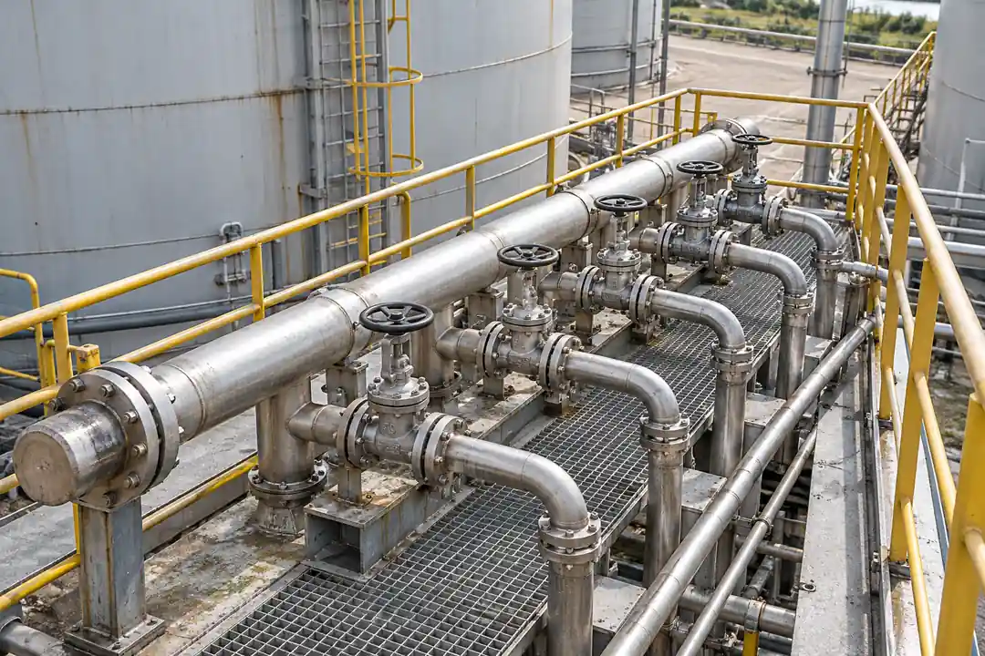
Oilfield pumping equipment in a representative outdoor production environment.

Connect Ethernet-capable gateways and workstations supporting oil, gas and process facilities. Define area classification, enclosure protection and approved installation location before selecting the network equipment; the reference switch does not establish hazardous-area suitability.

Oilfield equipment data links

Oilfield pumping equipment in a representative outdoor production environment.

Aggregate equipment-monitoring data at a field support cabinet and provide a defined Ethernet connection toward the site communications system.
Network connections
Ethernet-equipped monitoring gateways, local workstation and the agreed upstream connection.
Integration focus
Place the switch in an approved non-hazardous or appropriately protected installation. Process shutdown and protection functions remain independent.
Project checks
Check area classification, cabinet temperature, cable entry protection and upstream link loading.
Discuss this application ↗

Tank-farm supervisory links

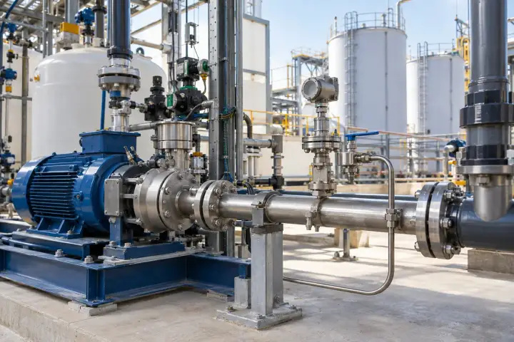
Tank-area pipework and service manifolds in an industrial process facility.

Bring compatible tank-area monitoring gateways onto the local site network for supervisory data access. Tank sensors connect through their approved gateway or controller.
Network connections
Ethernet ports on instrument gateways, a site data concentrator and the allocated uplink.
Integration focus
Transport the gateway data; tank level measurement, alarm decisions and overfill protection remain with their respective systems.
Project checks
Confirm segregation requirements, cabinet approval, data path and loss-of-link behaviour.
Discuss this application ↗

Pump and compressor package networks

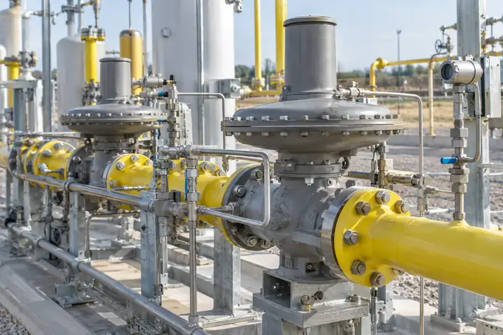
Process pumps, connected pipework and local service equipment.

Connect the Ethernet interfaces of packaged equipment controllers and service workstations within a defined equipment-area network.
Network connections
Package-controller Ethernet ports, maintenance terminal and site supervisory connection.
Integration focus
Keep equipment sequencing, permissives and protective trips within the package control system. Agree any access from other plant networks.
Project checks
Review port allocation, cable routing near drives, grounding and the expected traffic profile.
Discuss this application ↗

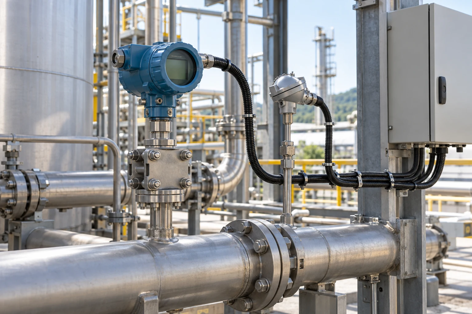
Gas-regulation station communications

A gas-regulation installation with valves, pipework and protected service areas.

Provide a local Ethernet aggregation point for approved station controllers and monitoring gateways in a suitable service enclosure.
Network connections
Station gateway or controller Ethernet interfaces and the specified backhaul device.
Integration focus
Treat the switch as network infrastructure. Pressure regulation, gas detection and emergency isolation remain separate application functions.
Project checks
Confirm hazardous-area boundaries, enclosure environment, approved supply and communications recovery.
Discuss this application ↗

Process instrument gateway aggregation

Process instrumentation and a local equipment enclosure beside industrial pipework.

Consolidate data connections from Ethernet-ready instrument gateways before handing the traffic to the plant network.

Network connections
Ethernet outputs from supported gateways; analogue and serial instruments require their own suitable interface equipment.
Integration focus
Document the gateway data definitions, approved traffic paths and application access policy as part of the plant-network design.
Project checks
Check gateway compatibility, address plan, traffic demand and the documented upstream connection.
Discuss this application ↗
02Metals & Mining5
An open surface mine illustrating the operating environment for protected site communications.

Support equipment-data networks in approved surface facilities, processing buildings and enclosed service rooms. Dust, vibration, heat, installation permissions and any underground requirements are project qualification items rather than implied product certifications.

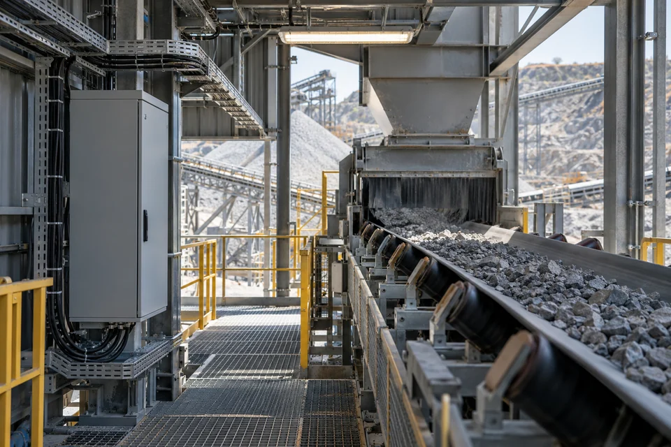
Surface-mine service networks

An open surface mine illustrating the operating environment for protected site communications.

Link monitoring gateways and service equipment within a protected surface-mine support installation. Provide the agreed connection to the wider site communications network.
Network connections
Ethernet-ready field gateways, maintenance equipment and a separately specified upstream device.
Integration focus
Keep equipment operating logic and safety systems outside the switching function; assess longer-distance links separately.
Project checks
Verify dust protection, installation vibration, cabinet thermal conditions and cable distances.
Discuss this application ↗

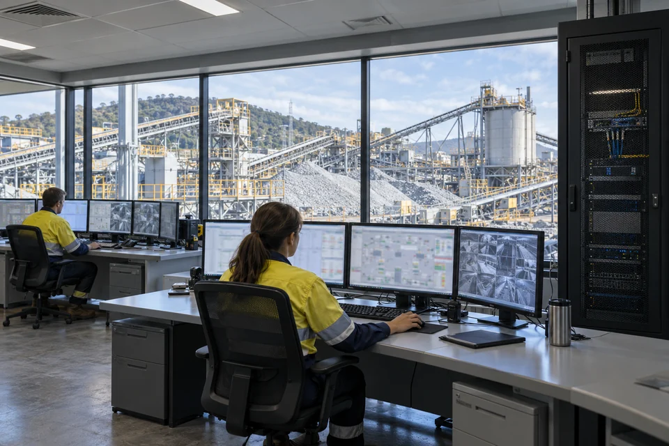
Conveyor-cell information links

Mineral conveyor transfer equipment with a protected service cabinet in a surface processing plant.

Connect conveyor controllers, condition-monitoring gateways and an operator terminal within the approved conveyor service network.
Network connections
Ethernet interfaces of the conveyor controller, monitoring gateway and supervisory terminal.
Integration focus
Transport permitted equipment data. Conveyor start permissives, pull-cord stops and safety interlocks remain within the approved control system.
Project checks
Check vibration exposure, cable containment, port allocation and traffic during equipment events.
Discuss this application ↗

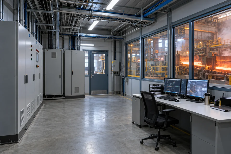
Mineral-processing workstation networks

Mineral-processing operator workstations and an enclosed communications rack.

Connect local supervisory workstations and Ethernet data concentrators serving a mineral-processing area.
Network connections
Control-room workstation interfaces, data concentrators and the documented plant-network connection.
Integration focus
Define the workstation traffic paths and application access within the approved plant-network and security architecture.
Project checks
Check aggregate traffic, addressing, upstream capacity and the separate network-security architecture.
Discuss this application ↗

Steelworks electrical-room networks

An enclosed steelworks electrical service room beside production equipment.

Provide Ethernet connectivity for monitoring gateways and maintenance equipment installed in a suitable steelworks electrical service room.
Network connections
Equipment gateways, service workstation and the agreed plant network connection.
Integration focus
Locate network equipment within its qualified environment; furnace heat, drive noise and production exposure require installation-specific assessment.
Project checks
Check enclosure temperature, grounding, cable separation and any site-specific EMC requirements.
Discuss this application ↗

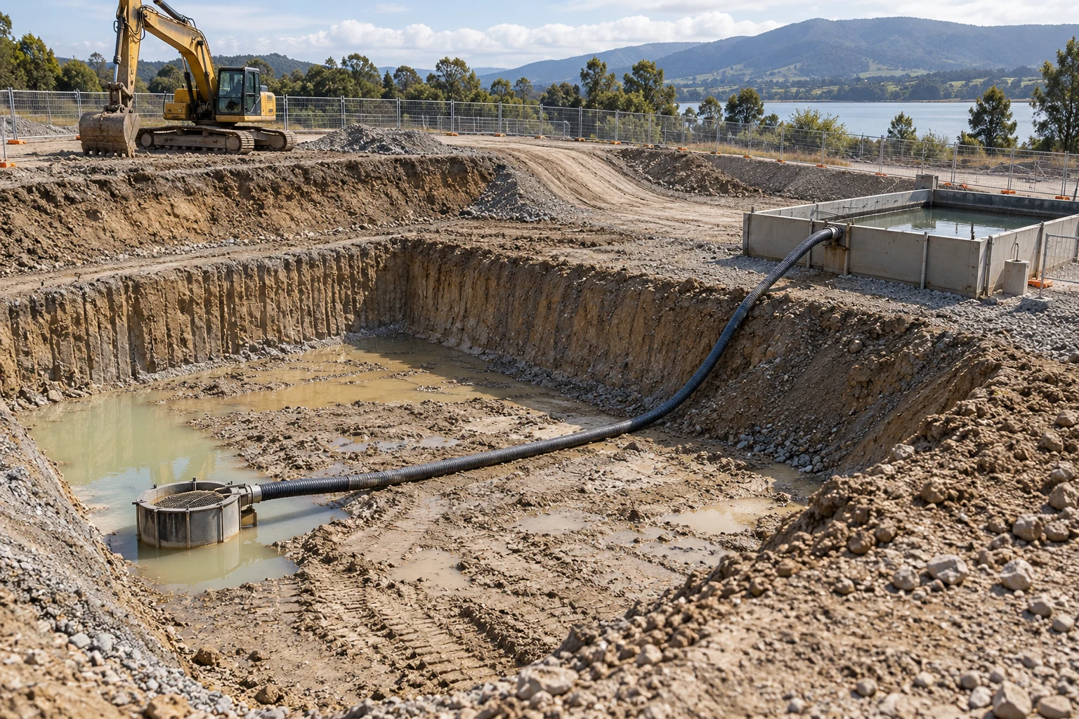
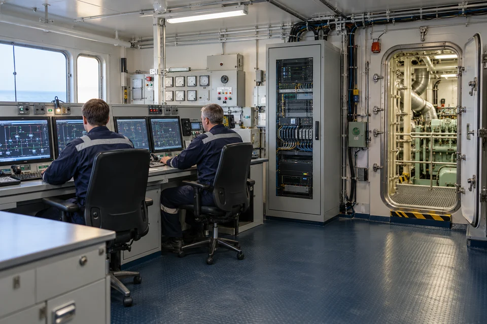
Mine-dewatering station links

A surface dewatering excavation and pumping environment at an industrial site.

Connect the Ethernet side of pump-station controllers and monitoring gateways to the surface communications system.
Network connections
Pump controller or gateway Ethernet ports and a separately selected upstream link.
Integration focus
Water-level sensing and pump sequencing remain with the station controls. Qualify any underground location and its required approvals separately.
Project checks
Review moisture protection, supply arrangement, cable route and response to link or power loss.
Discuss this application ↗
03Marine & Shipboard Systems5
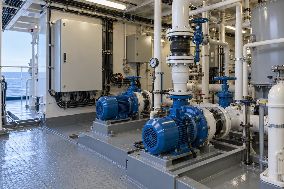
Shipboard machinery-monitoring workstations in an engine control room.

Develop Ethernet interconnection for selected shipboard and shore-service equipment. Confirm the vessel, installation zone and applicable qualification requirements before defining the supplied configuration. Ship-class approval, marine EMC and suitability for any navigation or safety function must be established for the assigned network role.

Machinery-monitoring workstations

Shipboard machinery-monitoring workstations in an engine control room.

Connect approved machinery-monitoring workstations and data gateways within the vessel equipment network.
Network connections
Ethernet interfaces on monitoring gateways, operator terminals and the agreed vessel-network connection.
Integration focus
Keep machinery protection and essential control functions within their approved systems. Confirm the permitted network role with the vessel integrator.
Project checks
Review applicable marine approvals, vibration, supply conditions, cabinet temperature and network access.
Discuss this application ↗

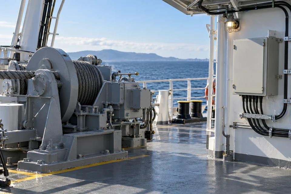
Auxiliary-service equipment networks

Marine auxiliary pumps with protected local equipment enclosures.

Interconnect Ethernet-capable monitoring gateways serving selected auxiliary pumps and service equipment in a suitable machinery-space enclosure.
Network connections
Approved controller or gateway Ethernet ports; field signals remain on their documented instrument interfaces.
Integration focus
Provide the defined data path without replacing equipment protection, local control or vessel alarm functions.
Project checks
Check enclosure location, condensation, cable support, grounding and applicable marine qualification.
Discuss this application ↗

Deck-service status networks

A vessel deck service enclosure beside protected equipment cable runs.

Link compatible deck-equipment monitoring gateways from a protected service enclosure to the agreed vessel data network.
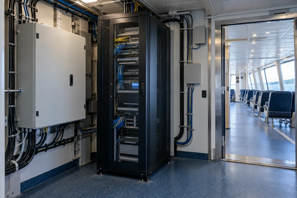
Network connections
Ethernet-ready status gateways and the specified upstream network interface.
Integration focus
Use a qualified protected installation for salt, water and environmental exposure. Do not expose the reference switch directly to deck conditions without approval.
Project checks
Verify enclosure protection, corrosion exposure, cable glands, supply and vessel installation requirements.
Discuss this application ↗

Passenger-service equipment networks

An enclosed ferry communications rack serving passenger-area equipment.

Connect selected passenger-service data equipment through an enclosed communications installation on a ferry or passenger vessel.
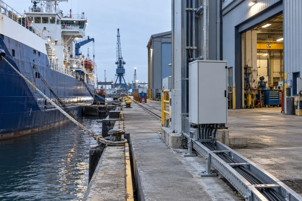
Network connections
Approved Ethernet service devices, local data equipment and the vessel integrator-defined uplink.
Integration focus
Specify service-network boundaries and the separate security architecture; do not extend this example to navigation or emergency systems.
Project checks
Review device load, service availability requirements, installation approvals and permitted access between networks.
Discuss this application ↗

Shipyard shore-service networks

A sheltered shipyard shore-service cabinet beside a vessel at berth.

Provide local Ethernet connectivity for maintenance workstations and equipment-data gateways at a protected quayside or workshop service point.

Network connections
Workshop workstations, service gateways and the documented yard-network connection.
Integration focus
Define shore-to-vessel access permissions and physical network boundaries before connecting maintenance equipment.
Project checks
Check temporary-connection control, weather protection, grounding and the approved cabinet supply.
Discuss this application ↗
04Energy & Renewables5
Solar arrays with service equipment in a representative generation site.

Connect Ethernet-ready equipment across renewable generation and supporting power facilities. Select each cabinet network around its endpoints, upstream path and environment; energy-control algorithms, protection and cloud services belong to their respective systems.

Solar inverter and logger networks

Solar arrays with service equipment in a representative generation site.

Aggregate Ethernet connections from compatible solar inverters, data loggers and site monitoring gateways inside a suitable plant service cabinet.

Network connections
Ethernet-equipped inverters or loggers and the project-specified backhaul device.
Integration focus
Agree inverter and logger data protocols, addressing and permitted supervisory exchanges with the plant integrator.
Project checks
Review endpoint count, uplink allocation, cabinet thermal conditions and expected data traffic.
Discuss this application ↗

Wind-equipment service networks

Wind turbines in a representative renewable-energy operating environment.

Connect selected condition-monitoring gateways and service equipment to an agreed wind-site data network.
Network connections
Ethernet-ready monitoring gateways, service terminal and the specified site connection.
Integration focus
Limit the installation to its qualified network role. Turbine protection, essential controls and any deterministic network requirements require separate assessment.
Project checks
Check vibration, installation temperature, cable routing and project-specific traffic requirements.
Discuss this application ↗

Battery-storage auxiliary data links

Battery-storage equipment and a protected service enclosure.

Connect approved Ethernet interfaces from auxiliary monitoring gateways and service workstations around a battery-storage installation.

Network connections
Ethernet outputs from the relevant monitoring or equipment controllers and the allocated upstream path.
Integration focus
Keep battery protection, fire systems and charge-discharge decisions within their approved systems; establish the permitted data exchange.
Project checks
Check network boundaries, enclosure conditions, supply compatibility and link-recovery requirements.
Discuss this application ↗

Hydropower monitoring-station networks

A reservoir and dam environment representing hydropower and water-site communications.

Link Ethernet-capable monitoring gateways and an operator terminal at an approved hydropower or reservoir service facility.
Network connections
Station monitoring gateway, local workstation and the separately specified site backhaul.
Integration focus
Carry supervisory data without assuming water-control logic, dam-safety functions or turbine protection.
Project checks
Confirm the installation environment, endpoint protocol compatibility and the upstream service architecture.
Discuss this application ↗

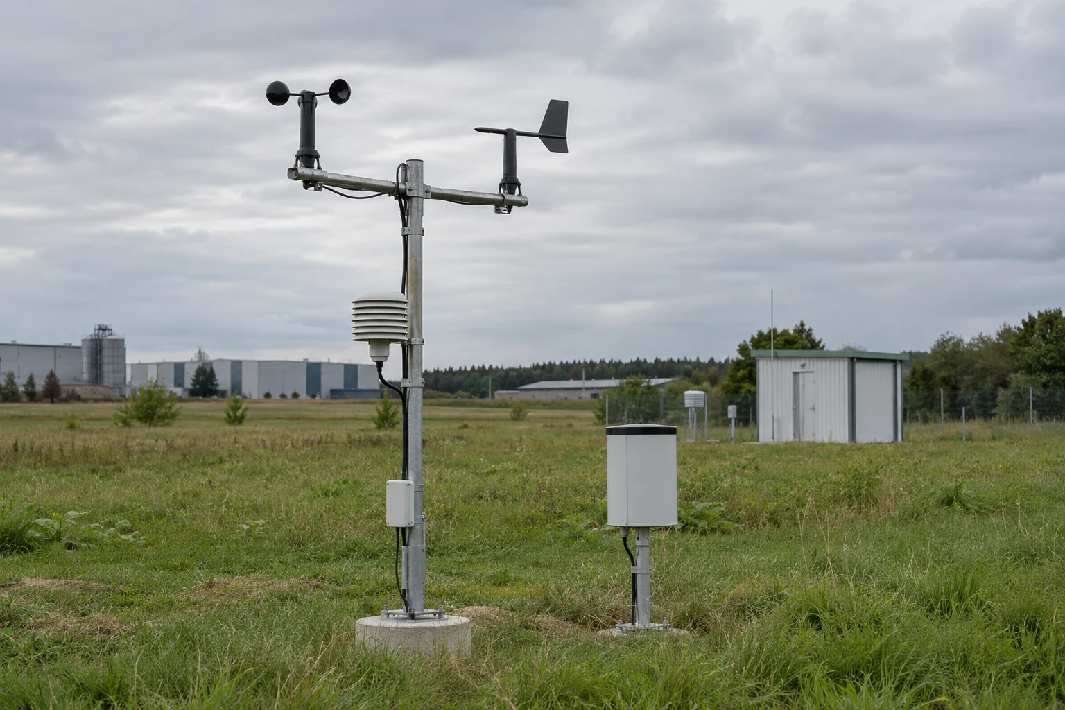
Renewable-site weather data aggregation

Weather observation instruments and protected site service enclosures.

Connect an Ethernet-ready weather logger or environmental gateway to the approved renewable-site data network.

Network connections
Weather-logger or gateway Ethernet output and the allocated site-network connection.
Integration focus
Agree the weather data definitions, update requirements and permitted exchange with the site monitoring application.
Project checks
Check logger interface compatibility, addressing, traffic demand and protected cabinet installation.
Discuss this application ↗
05Video & Site Surveillance5
A visible security camera covering an industrial production aisle.

Build a defined Ethernet path between compatible cameras, recorders and upstream equipment. Review stream loading and power each device through its approved supply; the reference configuration does not establish PoE, video recording, analytics or remote-access functions.

Production-area video networks

A visible security camera covering an industrial production aisle.

Connect Ethernet cameras covering a production aisle to the local recorder or agreed upstream network.
Network connections
Camera data ports, recorder interface and allocated Ethernet uplink; camera power is specified separately.
Integration focus
Coordinate the camera-to-recorder data path with the video-system design, including recording, retention and any analytics requirements.
Project checks
Calculate simultaneous stream demand, uplink loading and cable lengths; confirm the camera power design.
Discuss this application ↗

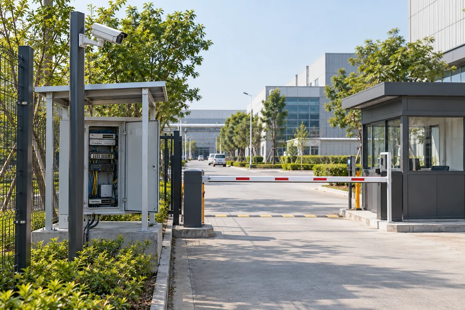
Entrance and gate video links

An industrial entrance with a pole-mounted camera and guard kiosk.

Aggregate compatible camera data connections from an industrial entrance at a protected local service point.
Network connections
Ethernet cameras, the site recorder or video network and the documented backhaul interface.
Integration focus
Define permitted links between the entrance video system and access-management equipment within the site network architecture.
Project checks
Check bandwidth, outdoor cabinet protection, surge-protection design and the approved network boundary.
Discuss this application ↗

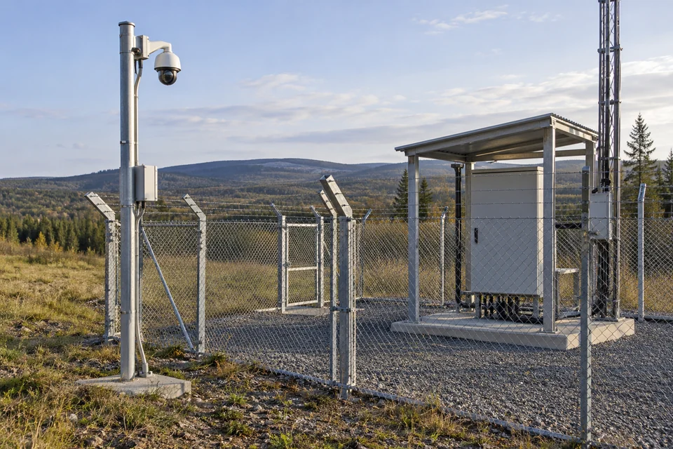
Remote-facility perimeter video

A remote facility perimeter camera and protected communications cabinet.

Connect perimeter-camera data streams to the selected recorder or remote communications device within a protected site cabinet.
Network connections
Ethernet camera interfaces and separately specified recording or backhaul equipment.
Integration focus
Document the backhaul, recorder and approved remote-viewing path as parts of the site network architecture.
Project checks
Review aggregate bitrate, uplink availability, local recording arrangements and the independent camera power supply.
Discuss this application ↗

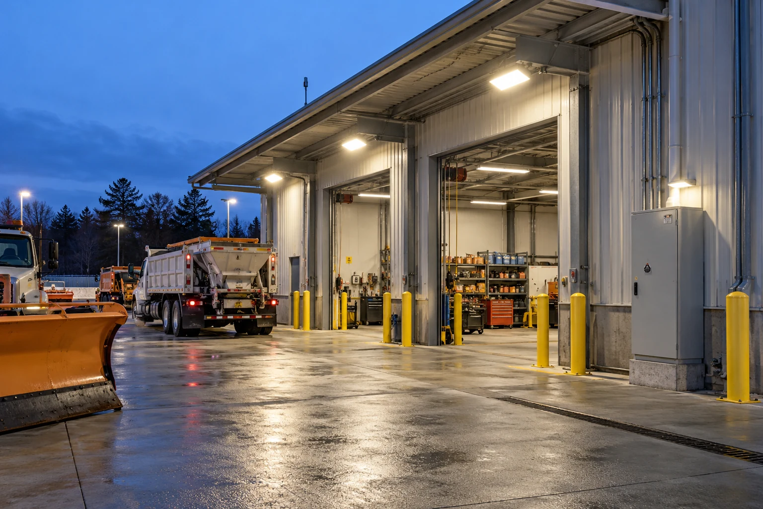
Loading-bay surveillance links

An industrial loading-bay service area illustrating a local surveillance-network location.

Provide a local data connection for cameras covering loading bays, yard entrances and nearby service areas.

Network connections
Ethernet cameras and the approved recorder or building-network connection.
Integration focus
Assign ports to camera endpoints and the uplink, then agree the recording and event-handling workflow with the video-system integrator.
Project checks
Check concurrent streams, uplink loading, installation cable routes and enclosure conditions.
Discuss this application ↗

Port-yard video aggregation

A container terminal with freight-handling equipment and operational yard space.

Interconnect selected Ethernet video endpoints serving a port logistics zone from a protected equipment location.
Network connections
Approved camera interfaces, video recorder or network node and the specified upstream device.
Integration focus
Coordinate the local camera network with the separately selected yard backbone, including its required distance and upstream media.
Project checks
Review stream demand, cable distance, cabinet protection, grounding and port-site installation requirements.
Discuss this application ↗
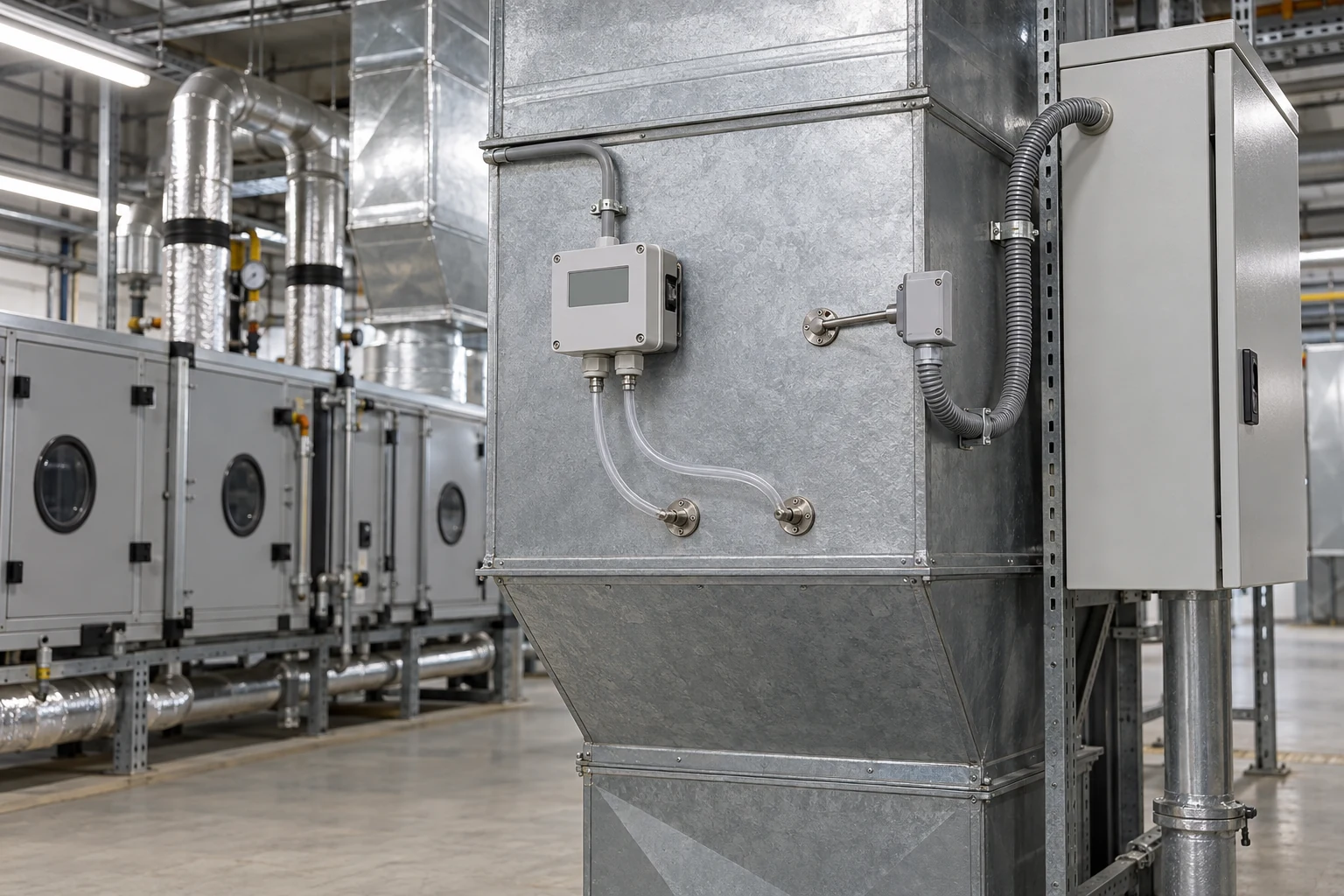
06Smart Buildings5
Air-handling equipment and protected building-services enclosures.

Connect Ethernet-ready building gateways, plant controllers and service workstations through a defined local infrastructure. Building protocols, control sequences, remote access and platform functions remain with the selected endpoints and building-management system.

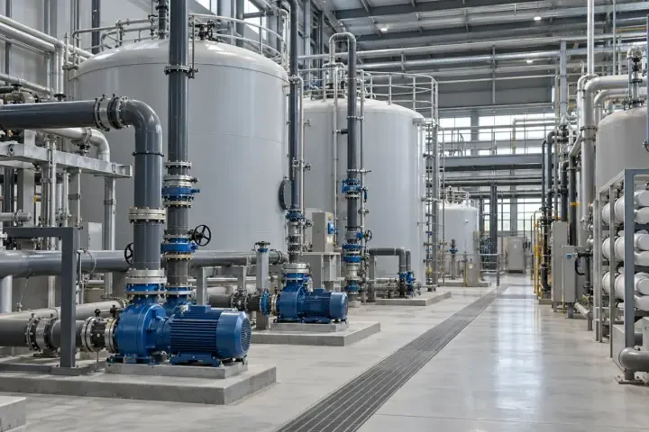
Building-services gateway aggregation

Air-handling equipment and protected building-services enclosures.

Bring compatible building-services gateways and an operator terminal onto the approved facilities network.
Network connections
Ethernet outputs from gateways serving HVAC or other building equipment; serial buses require their own suitable gateway.
Integration focus
Agree the building protocols, gateway point mapping and approved application access with the building-management integrator.
Project checks
Check addressing, gateway compatibility, port allocation and permitted access to the facilities network.
Discuss this application ↗

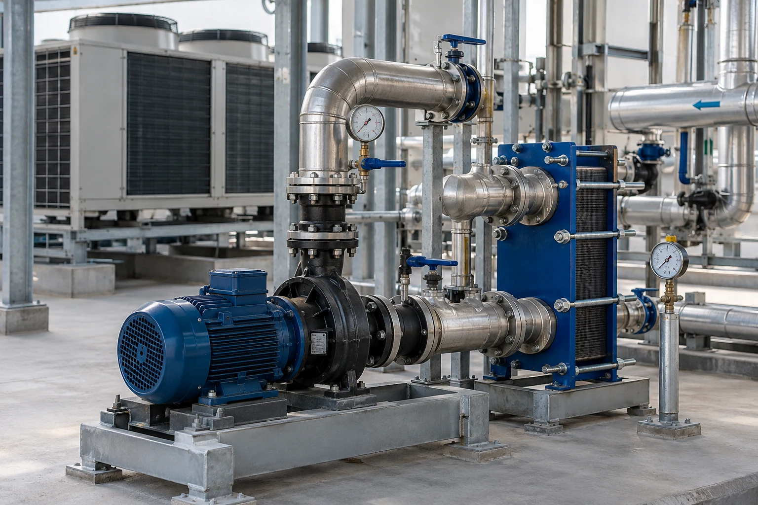
Plant-room utility networks

An indoor plant room with pumps, pipework and service equipment.

Connect Ethernet-ready metering and equipment gateways serving a building water or utility plant room.
Network connections
Meter gateway and plant-controller Ethernet interfaces, plus the agreed upstream connection.
Integration focus
Define meter identities, gateway data maps, update requirements and the approved building-services data path.
Project checks
Review moisture protection, cable separation, data demand and installation access.
Discuss this application ↗

Chilled-water service links

Cooling equipment and pump pipework in a building-services installation.

Interconnect compatible cooling-plant gateways and a maintenance workstation at a suitable plant-room network point.

Network connections
Chiller or pump-controller Ethernet interfaces, gateway ports and the building-network uplink.
Integration focus
Coordinate cooling-plant data points, equipment-gateway connections and the approved maintenance-access path.
Project checks
Verify enclosure temperature, grounding near drives, endpoint compatibility and the maintenance access path.
Discuss this application ↗

Campus facilities supervisory access

A commercial building workspace representing facilities-supervision access.

Connect a facilities workstation and approved building-data endpoints to the agreed campus service network.
Network connections
Facilities workstation, Ethernet data gateways and the allocated upstream network connection.
Integration focus
Agree authorized facilities-workstation access and the approved boundaries between campus business and building-services networks.
Project checks
Check authorized access, addressing, endpoint demand and the agreed network boundaries.
Discuss this application ↗

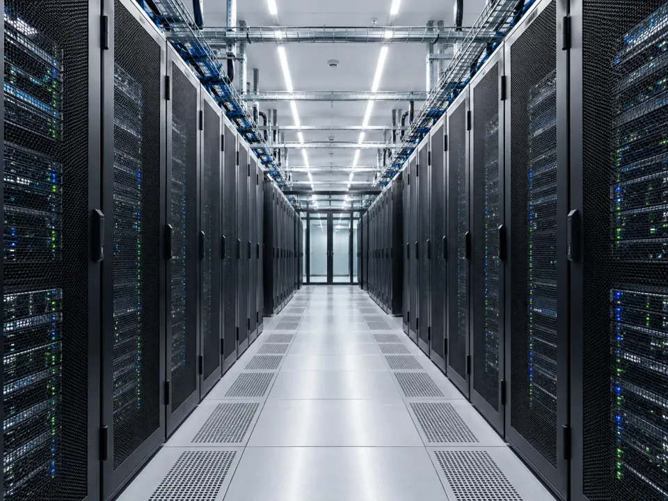
Data-centre facilities networks

Server racks and service aisles in a representative data-centre environment.

Connect selected Ethernet gateways supporting data-centre facility monitoring and maintenance in an appropriate service network.
Network connections
Facility-monitoring gateway interfaces, local service workstation and the documented upstream path.
Integration focus
Use the facilities network design to define monitoring endpoints, authorized maintenance access and separation from production IT traffic.
Project checks
Review network separation design, installation temperature, device loads and site availability requirements.
Discuss this application ↗
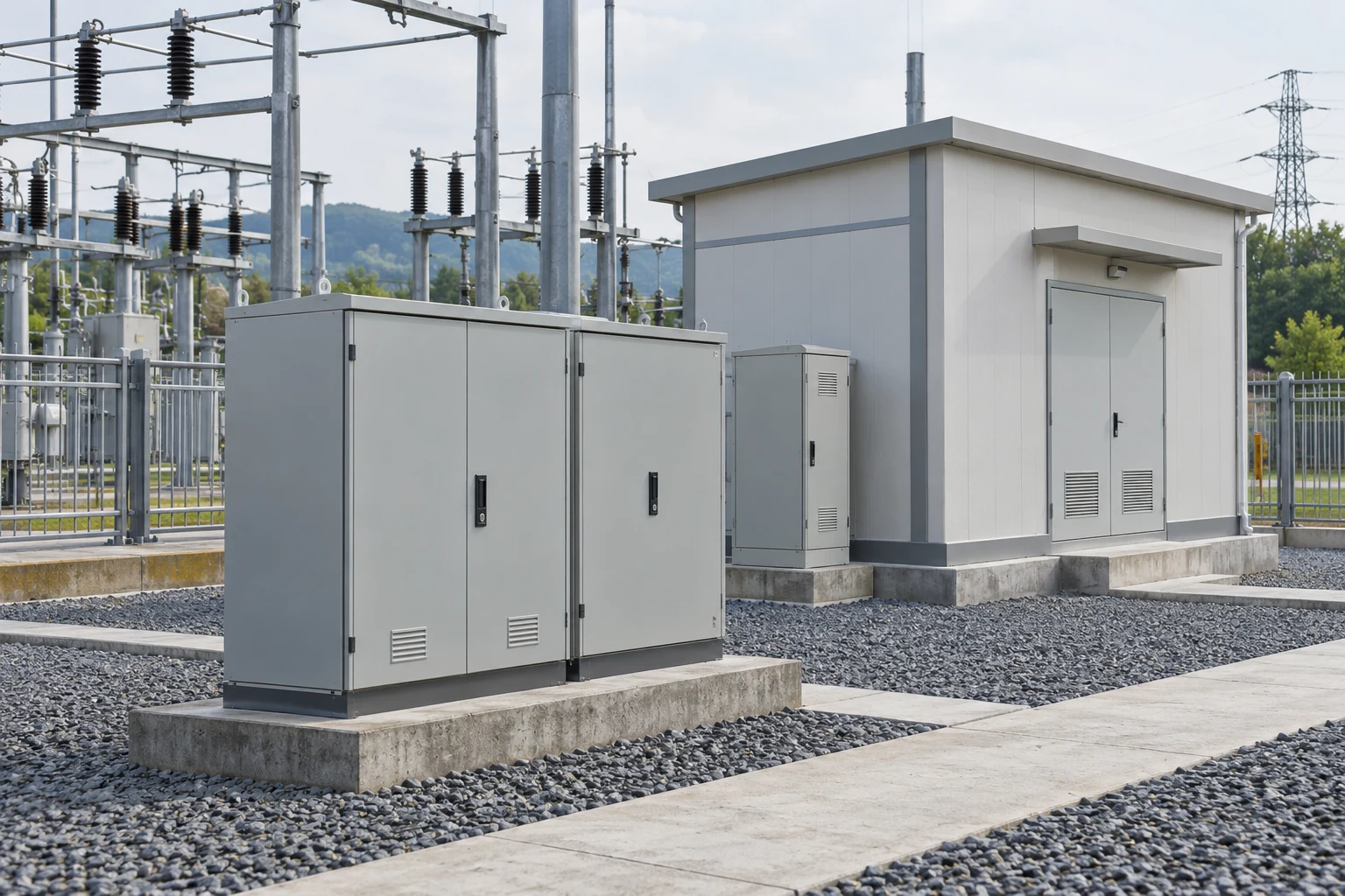
07Utility & Grid Facilities5
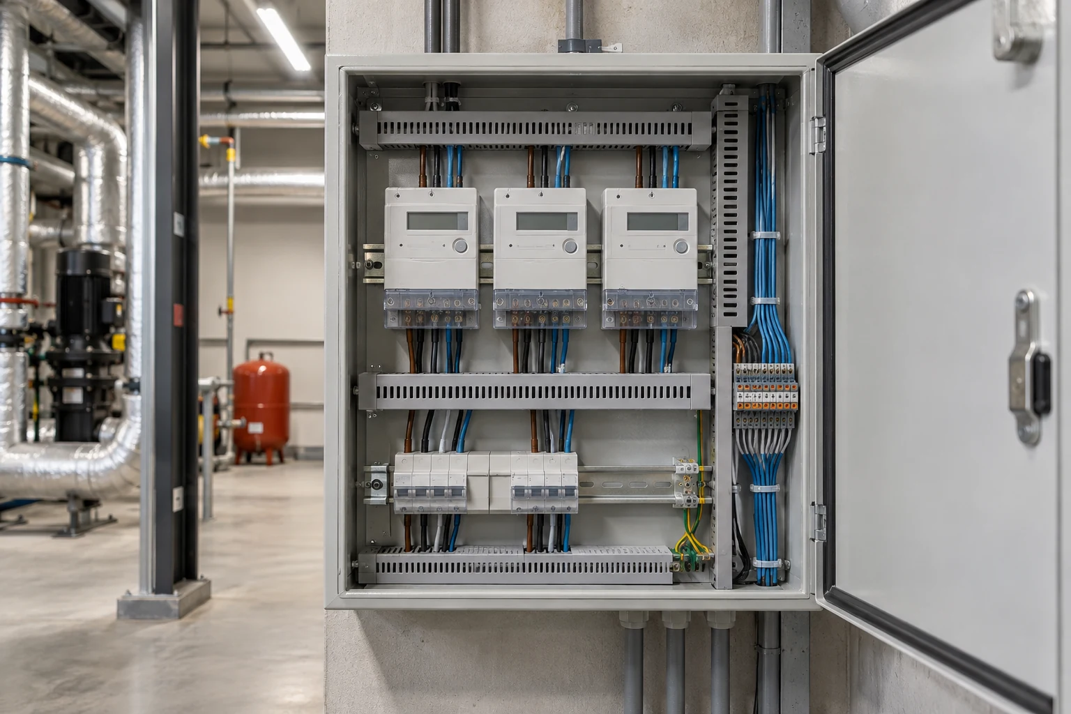
Substation service enclosures and outdoor electrical infrastructure.

Connect selected metering, equipment-condition and maintenance endpoints in electrical utility facilities. Define the approved auxiliary network role and verify applicable environmental, EMC and sector requirements; these examples do not establish protection-network, process-bus or substation certification.

Substation auxiliary communications

Substation service enclosures and outdoor electrical infrastructure.

Connect permitted Ethernet gateways and service equipment within an approved auxiliary network at a substation facility.
Network connections
Auxiliary monitoring gateway, maintenance terminal and the integrator-defined upstream connection.
Integration focus
Exclude protection or time-critical process-bus roles unless separately qualified. This reference does not establish IEC 61850 or substation certification.
Project checks
Review applicable EMC and sector requirements, isolation boundaries, grounding and authorized access.
Discuss this application ↗

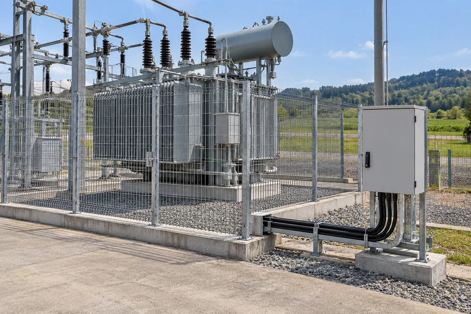
Distribution-room metering gateway networks

Electricity metering equipment and protected distribution-service wiring.

Aggregate Ethernet connections from approved metering gateways and a local energy-data workstation in an electrical distribution service area.
Network connections
Meter-gateway Ethernet outputs and the agreed utility supervisory connection; serial meters use their own suitable gateway.
Integration focus
Define measurement identities, units, data maps and authorized exchanges in the metering system. Revenue-metering approval is a separate endpoint requirement.
Project checks
Review gateway compatibility, electrical separation, grounding, traffic demand and the permitted utility network boundary.
Discuss this application ↗

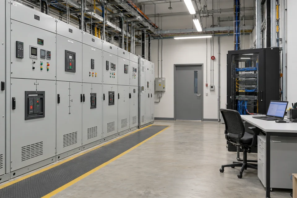
Power-equipment condition data links

Power-transformer monitoring equipment and a protected auxiliary service enclosure at a utility site.

Connect Ethernet-ready condition-monitoring gateways serving transformers or other electrical equipment to the approved auxiliary data network.
Network connections
Condition-monitoring gateway Ethernet interface and the utility-defined monitoring connection.
Integration focus
Transport monitoring information only. Protection trips, essential control and time-critical process-bus functions require their own qualified architecture.
Project checks
Confirm endpoint protocols, monitoring-data demand, installation clearances, EMC requirements and approved enclosure location.
Discuss this application ↗

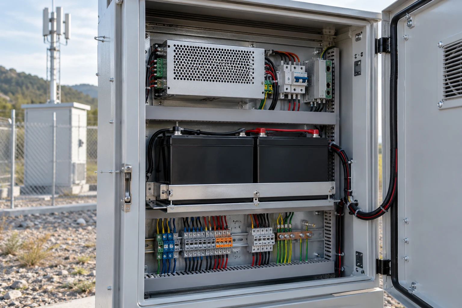
Utility maintenance-workstation access

An authorized maintenance workstation in a utility electrical service room.

Provide a defined Ethernet connection for an authorized maintenance workstation and selected utility equipment-data gateways.
Network connections
Maintenance-workstation Ethernet port, approved data gateways and the allocated service-network connection.
Integration focus
Document authorized access, permitted endpoints and the separate network-security controls before connecting service equipment.
Project checks
Check access procedure, network boundaries, addressing, cabinet conditions and the handling of temporary maintenance connections.
Discuss this application ↗

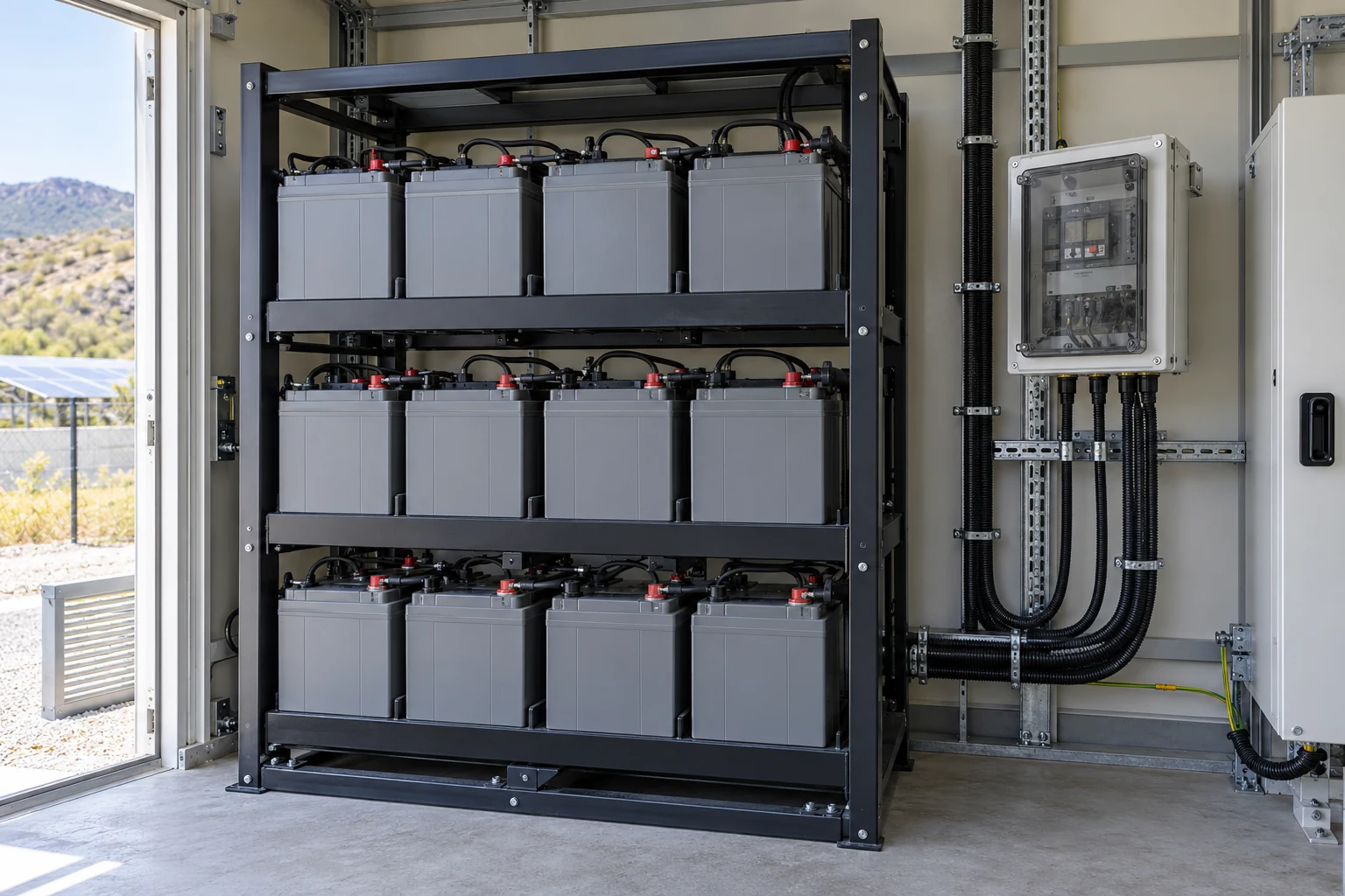
DC auxiliary-supply monitoring links

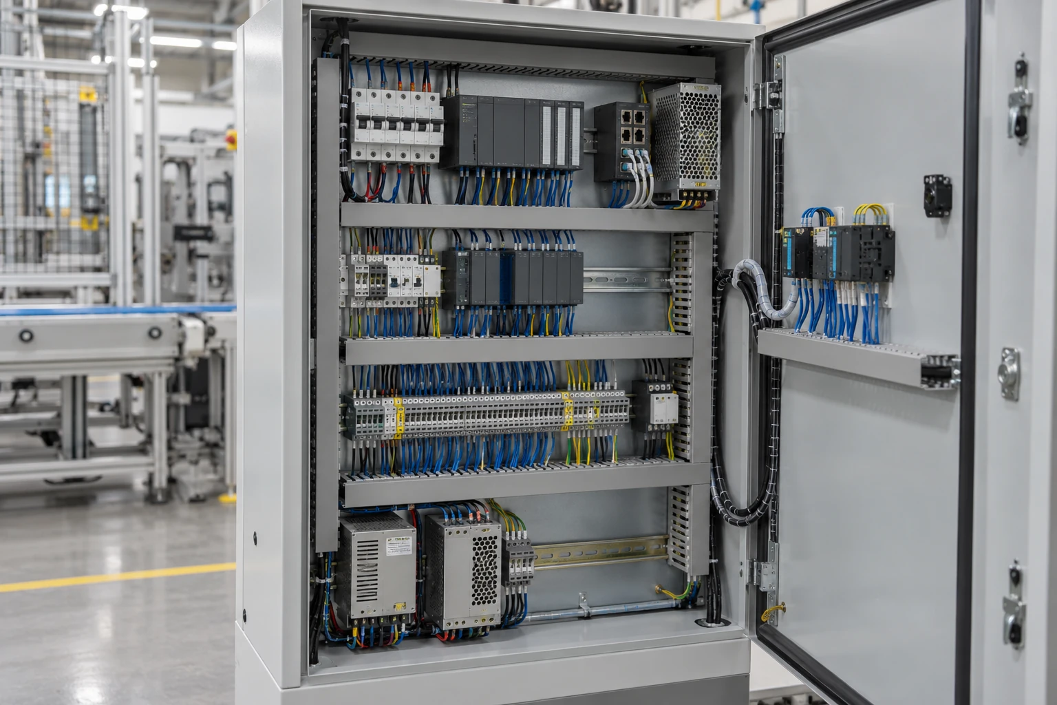
An enclosed DC auxiliary power and communications service cabinet.

Connect compatible Ethernet gateways reporting auxiliary DC power-system status within an approved utility service network.
Network connections
Ethernet outputs from DC monitoring or power-data gateways and the agreed supervisory endpoint.
Integration focus
Define the status data and alarm exchange at the monitoring endpoints. Battery protection, DC distribution protection and essential supply functions remain independent.
Project checks
Confirm gateway electrical compatibility, grounding, protected installation and behaviour during auxiliary-supply or network interruptions.
Discuss this application ↗
08Industrial Automation5
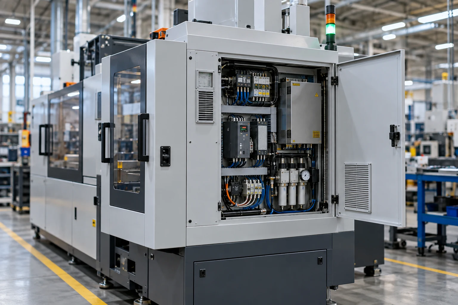
A production control cabinet containing PLC and interface equipment.

Connect compatible PLCs, operator terminals, machine gateways and maintenance equipment within a defined production network. Verify device protocols, traffic demand and any real-time or security requirements before selecting the final network architecture.

PLC and HMI cell networks

A production control cabinet containing PLC and interface equipment.

Interconnect compatible Ethernet PLCs, operator terminals and data gateways serving an individual production cell.
Network connections
PLC and HMI Ethernet ports, monitoring gateway and the agreed cell-network uplink.
Integration focus
Confirm protocol compatibility and timing requirements with the controls integrator. The reference does not establish deterministic performance or safety-network suitability.
Project checks
Review traffic loading, control-system requirements, loop-free topology and device addressing.
Discuss this application ↗

Machine monitoring and service networks

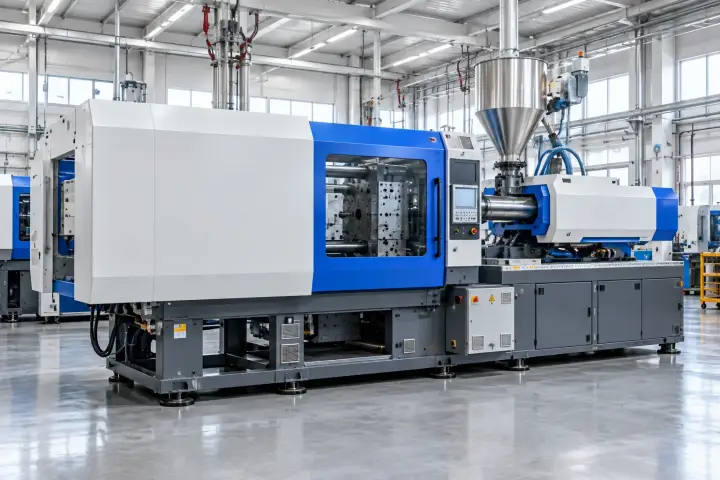
A machine tool with accessible local control and service equipment.

Provide an Ethernet connection point for a machine controller, condition-monitoring gateway and authorized maintenance workstation.
Network connections
Approved machine-controller interface, monitoring gateway and the specified service connection.
Integration focus
Define authorized service access, permitted machine-data exchanges and the monitoring-gateway point list with the machine supplier.
Project checks
Check access permissions, cable routing, electromagnetic environment and the endpoint traffic profile.
Discuss this application ↗

Production-equipment data collection

Production machinery on a representative factory floor.

Connect Ethernet-ready machine gateways and data-collection equipment to the documented production information network.

Network connections
Equipment data-gateway ports, local collection server or terminal and the allocated upstream connection.
Integration focus
Define endpoint protocols, data ownership and processing responsibilities in the production data-collection design.
Project checks
Check endpoint count, gateway protocol support, uplink allocation and traffic during production events.
Discuss this application ↗

Electronics-production inspection links

Electronics-production equipment working over circuit-board assemblies.

Interconnect compatible inspection workstations and equipment-data interfaces in an electronics-production area.
Network connections
Ethernet-ready inspection equipment, workstation and agreed production-network connection.
Integration focus
Agree the inspection-data volume, transfer bursts and required application performance with the equipment supplier.
Project checks
Check aggregate demand, endpoint protocol settings and the documented uplink capacity.
Discuss this application ↗

Compressor and utility-skid networking

Compressed-air service equipment, receiver vessel and connected pipework.

Connect the Ethernet interfaces of utility-skid controllers, monitoring gateways and service equipment to the plant network.

Network connections
Controller and gateway Ethernet ports with the approved supervisory or maintenance connection.
Integration focus
Agree utility-skid data mapping, monitoring endpoints and the permitted supervisory and maintenance connections.
Project checks
Confirm enclosure conditions, drive-related cable separation, supply compatibility and the agreed traffic path.
Discuss this application ↗

REFERENCE & PROJECT SPECIFICATION

A clear reference.
An agreed configuration.

Use the HT7008 eight-port reference to start the specification. The reference covers port count, link speeds, enclosure and operating temperature. The agreed project documentation defines the delivered configuration and the remaining electrical and network details.

Product reference

HT7000 Series — Product reference
Product familyHT7000 Series industrial Ethernet switches
Illustrated modelHT7008
Port arrangement8 × RJ45 copper Ethernet ports; any upstream link uses a port within this total.

Ethernet connectivity

HT7000 Series — Ethernet connectivity
Supported link speeds10/100/1000 Mbps auto-negotiation
Flow controlIEEE 802.3x
Port allocationDefine endpoint links, upstream connection and spare-port requirements in the project port schedule.
Application trafficVerify the required traffic with the connected devices. Link rate is not an end-to-end throughput or latency guarantee.

Power and status

HT7000 Series — Power and status
Nominal DC supply values12 / 24 / 48 V DC
Input arrangementConfirm the permitted voltage range, input circuits, source priority or transfer behaviour and protection requirements for the supplied version.
Power consumptionObtain the specified consumption and starting requirements for cabinet power sizing.
IndicatorsPower and port-side indicators are shown. Confirm their meanings in the supplied operating instructions.

Mechanical and environmental

HT7000 Series — Mechanical and environmental
EnclosureAluminium alloy; external cooling fins
Operating temperature-40 to +75 °C
InstallationConfirm mounting method, dimensions, cable access, earthing and thermal clearances for the ordered configuration.
EMC integrationThe reference includes EMC protection. Confirm the applicable test standards, levels, installation conditions and supporting records.
Site protectionSpecify the installation enclosure and any required ingress, corrosion, hazardous-area or sector-specific qualification.

Customization and delivery

HT7000 Series — Customization and delivery
Project inputsEndpoint and port list, traffic requirements, upstream network, DC supply, cabinet conditions and destination requirements.
Customization scopeAgree the hardware, network-function requirements, product identification and documentation scope before design approval.
Configuration recordDocument the approved model, hardware version and any supplied settings or software scope.
VerificationAgree the functional, power, temperature, EMC and application-network checks appropriate to the project.

Choose the supplied configuration against the complete installation design. Product-level features, site protection, sector approvals and network performance must be documented for the selected project.

PROJECT INTEGRATION

Your equipment network. An agreed integration scope.

Place the switch within the project network design. It provides local Ethernet connectivity; the connected endpoints, upstream router or gateway and receiving systems define the wider data path, application services and operating responsibilities.

Network design: record the physical links, endpoint addresses, traffic paths and any separation or security requirements in the installation design. Use equipment with the required documented functions.

Power and installation: match the supplied input arrangement to the cabinet supply, earthing, cable routing and local thermal conditions. Confirm any redundancy requirement separately for power and network paths.

Project delivery: agree the port map, approved hardware and any software scope, product identification, installation documents and acceptance records before handover.

ANSWERS FOR YOUR PROJECT

Practical questions.
Before the network is built.

Answers for ports, traffic, power, installation conditions and industrial switch customization.

What is the relationship between HT7000 and HT7008?

HT7000 is the industrial Ethernet switch series. HT7008 is the eight-port model shown on this page. Use its reference configuration to start a project discussion, then confirm the exact supplied version and agreed customization in the ordering specification.

How many equipment links can the eight-port reference provide?

HT7008 has eight RJ45 ports in total. An upstream Ethernet connection also occupies one of these ports. Allocate endpoint links, upstream connections and spares together; do not count an additional unlisted uplink.

Does a Gigabit port guarantee Gigabit application throughput?

10/100/1000 Mbps describes the supported link speeds. Actual end-to-end performance also depends on the endpoints, cable installation, traffic pattern and other network equipment. Confirm the required application traffic and performance during project validation.

What does IEEE 802.3x mean here?

IEEE 802.3x refers to Ethernet flow control. It does not by itself establish traffic prioritization, deterministic timing or loss-free application delivery. Evaluate flow-control behaviour with the intended endpoints and traffic.

How should the DC supply be specified?

The reference lists 12, 24 and 48 V DC nominal supply values. Obtain the permitted input-voltage range, wiring schedule, input-circuit arrangement, consumption and protection details for the supplied version. The three nominal values alone do not define a continuous voltage range or a number of independent power inputs.

What does the -40 to +75 °C range apply to?

It is the operating-temperature range given for the switch reference. Check the conditions at the installation position inside the enclosure, including local heat sources and cooling. Confirm the applicable environmental and test conditions for the ordered configuration.

Are management functions, PoE or fibre ports included?

The documented HT7008 reference covers eight copper data ports. Specify any management, powered-device supply or fibre-connection requirement in the project brief. The written configuration proposal will identify the hardware and functions included in the ordered version.

Does redundant power also provide a redundant network?

Power-source arrangements and network-path resilience are separate design decisions. Agree the actual power-input circuits and transfer behaviour, then specify any network-recovery requirement independently. Do not create a loop without the required documented network functions.

Can the switch connect PLC, HMI and video equipment?

Compatible Ethernet endpoints can be included in the project port schedule. The endpoints still define their protocols and applications. Validate the traffic profile and any timing requirements; the switch reference does not establish protocol conversion or a safety-control function.

Can it be used outdoors, on ships or in hazardous areas?

Assess the complete installation against its enclosure, temperature, moisture, corrosion and regulatory requirements. The application examples are project contexts, not claims of outdoor ingress protection, marine approval, explosion protection or utility-sector certification. Obtain the required model-specific evidence before selection.

How does it fit into remote monitoring?

The switch connects local Ethernet equipment. Remote access and monitoring services depend on the connected router or gateway, endpoint software, receiving platform and project security design. Define that complete data path during integration; no built-in cellular or cloud-monitoring service is specified here.

What should an industrial switch customization brief include?

Provide the endpoint and port list, upstream network arrangement, traffic and timing needs, supply details, enclosure conditions, mounting constraints and destination requirements. Add requested network functions, product identification and documentation needs so the proposal can define the development, verification and delivery scope.

LET'S TALK ABOUT YOUR PROJECT

Your network.
A defined switch configuration.

Share the network drawing, endpoint list and installation conditions. We will review the HT7008 reference and the requested customization against the project requirements, then define the proposed configuration and verification scope.

sales@hitelecom.cn ↗

HT7000 Series Industrial Ethernet Switch

Review your brief, then send it with your email app.