


Custom industrial-site camera.Define the view.
Specify the image.

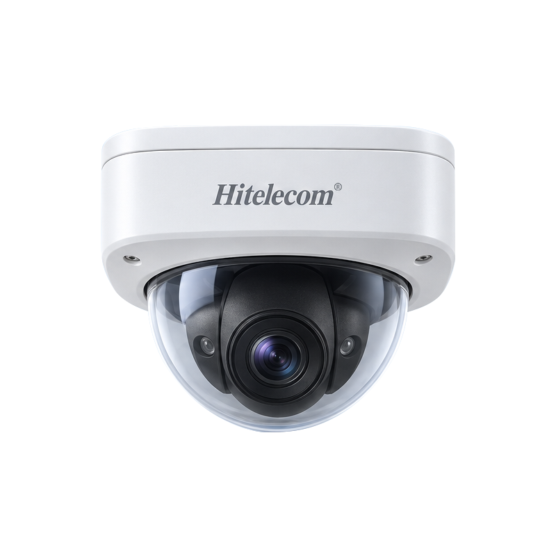
Hitelecom H100-HTC1800 dome-camera reference with a white housing and dark transparent dome
H100-HTC1800 · dome-camera reference

Use the Hitelecom H100-HTC1800 dome-camera reference as a starting point for industrial-site visual monitoring. Develop the configuration around the scene, observation distance, lighting, installation conditions and receiving system. Agree the optics, imaging, power and connection requirements, then validate the proposed configuration against representative site conditions.

H100-HTC1800Custom camera referenceA defined starting point for the project
Dome formatDome-camera design referenceCoordinate coverage and the installation
Project configurationRequirements agreed before releaseDefine imaging, power and system integration

CUSTOMIZATION FOCUS

A useful view.
A defined imaging task.

Turn the observation objective, scene and receiving workflow into an agreed camera specification and a practical validation plan.

Observation-led specification

Start with a visible target and an operational question. Define the image evidence an operator needs to understand the equipment or site activity, then turn it into measurable project requirements.

Coverage and mounting review

Coordinate the scene width, working distance, viewing angle and mounting position. Review obstructions and service access before approving the proposed optical and mechanical arrangement.

Lighting and contrast assessment

Provide representative scene images and lighting conditions, including glare, shadows and relevant low-light periods. Use them to define and evaluate the required imaging behaviour.

Image detail and motion requirements

Specify the target detail, movement and useful update behaviour for the observation task. Agree resolution, lens, exposure and frame-rate requirements as part of the camera configuration.

Power and connection planning

Define the supply, electrical interfaces and connection method for the installation and receiving equipment. Confirm cable routing, associated device loads and the approved wiring documentation.

Viewing and recording workflow

Describe who uses the images and whether viewing, transfer or recording is required. Match the camera configuration to the selected receiving system and define retention and access requirements.

Environment and enclosure review

Review the installation temperature, moisture, dust, cleaning conditions and mechanical exposure. Establish the required enclosure and supporting verification for the final camera assembly.

Documented customization and delivery

Agree the camera configuration, product identification, any associated software scope and acceptance criteria before design approval. Record the delivered version and its supporting installation and test documents.

IMAGING & INSTALLATION BRIEF

Define the scene.
Coordinate the system.

Describe the observation requirement, installation position and receiving equipment together. These inputs guide the camera configuration and the project acceptance criteria.

Imaging

Start with the observation task

Define what the operator needs to see, the target distance, scene width and relevant movement. Match image detail, coverage and lighting requirements to that task before choosing the imaging configuration.

  • Equipment state and operating-area context
  • Lens coverage and mounting-position review
  • Agreed image-detail and motion acceptance criteria
Installation

Coordinate the physical location

Review the mounting surface, viewing direction, service access and environmental exposure. Specify the camera assembly, cable entry, installation hardware and power arrangement for the approved location.

  • Mounting height, clearance and viewing obstructions
  • Site lighting, reflections and local conditions
  • Documented electrical and mechanical arrangement
Integration

Define where images are used

Identify the receiving equipment and whether the project requires live viewing, image transfer, recording or a combination. Agree the supported interfaces and application workflow in the configuration proposal.

  • Selected receiver and viewing workflow
  • Recording, retention and access requirements
  • End-to-end compatibility and acceptance testing

FROM SCENE TO DELIVERED CONFIGURATION

Describe. Specify.
Validate the actual view.

Use representative scenes and a documented project specification to connect the observation task with the delivered camera assembly.

01

Describe the scene

Share the observation target, scene dimensions, distance, mounting position and representative lighting. Explain what an operator must be able to confirm from the image.

02

Agree the configuration

Review optics, imaging behaviour, power, connection method and receiving equipment. Put the approved hardware, software scope and verification criteria into the project specification.

03

Evaluate a representative setup

Assess the agreed sample or configuration with realistic lighting, movement and receiver conditions. Review usable detail, coverage, integration and installation behaviour before release.

04

Document the delivered assembly

Hand over the configuration record, installation instructions and agreed test evidence. Identify the receiving system, operating responsibilities and maintenance access for the completed installation.

APPLICATIONS

Visual context.
Across the operation.

Explore eight application areas and 40 visual observation tasks. Each task begins with a scene an operator needs to understand, then identifies the view and integration requirements to review. These are representative project uses; the selected camera configuration and installation must be validated for the actual location.

8 application areas / 40 observation tasks

Representative environments, not camera footage or customer installations. Images do not demonstrate product imaging performance.
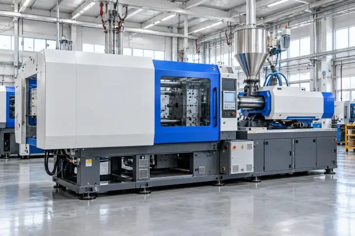
01Manufacturing & Workshop Areas5
Production equipment and access aisles across an industrial factory floor.

Frame production activity, equipment access and service areas for human visual review. Define the observation task and viewing conditions first; the camera reference does not establish machine-vision inspection, dimensional measurement or safety-control performance.

Production-area overview

Production equipment and access aisles across an industrial factory floor.

Give operators a visual overview of the selected production area to support routine coordination and review of visible activity.
View requirements
Define the area to be included, observation distance and receiving viewing system.
Observation scope
Agree the visible activities that matter to the operator and the surrounding areas that should stay outside the view.
Project checks
Review representative operating conditions, obstructions, reflections and changes in lighting.
Discuss this application ↗

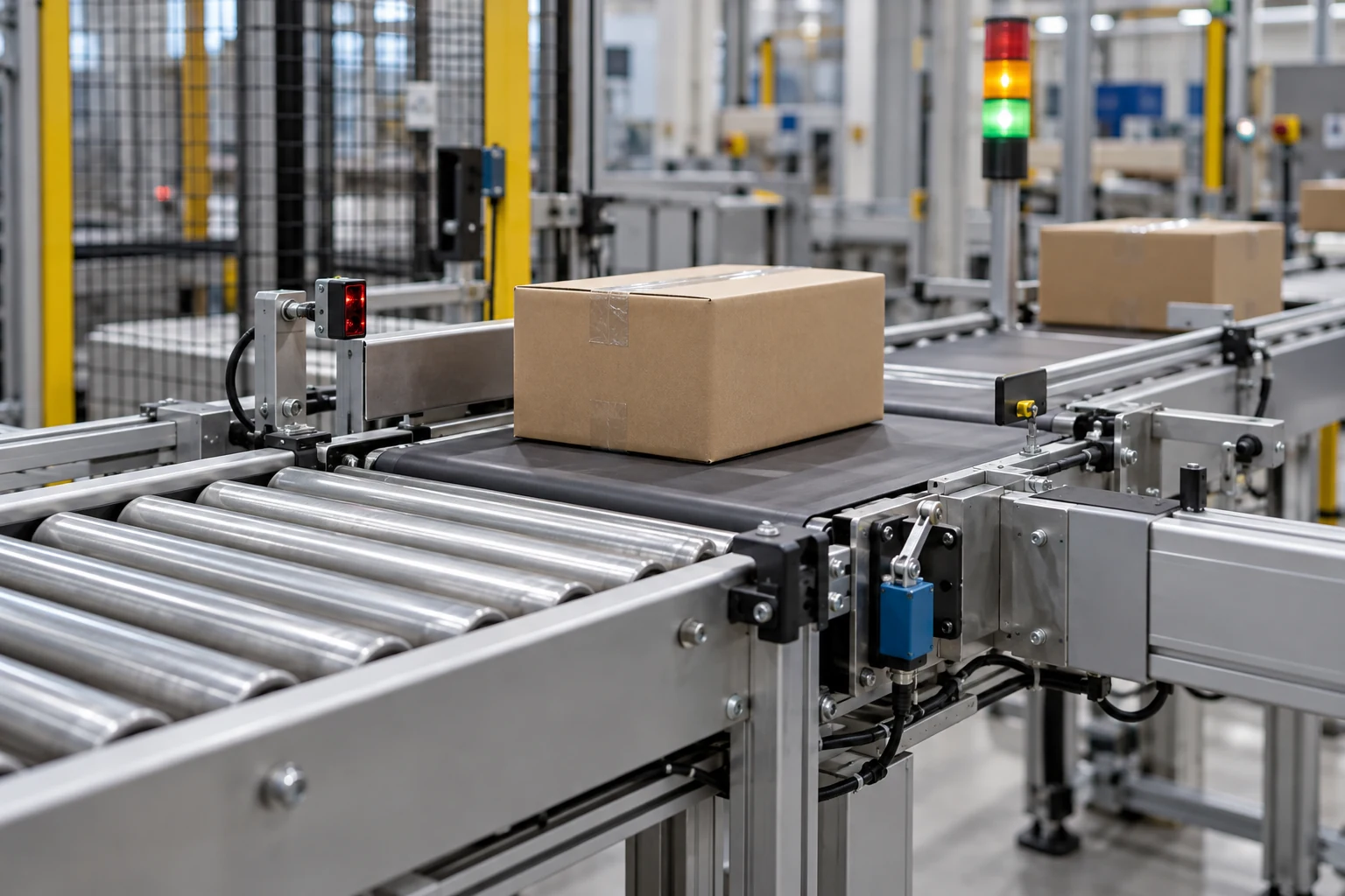
Conveyor-transfer context

A conveyor handling parcels in a production or logistics transfer area.

Provide visual context around a conveyor transfer area when staff need to review material movement or attend a service request.
View requirements
Specify the transfer point, expected movement and the image-delivery route required for review.
Observation scope
Frame the transfer area and adjacent access space without placing the installation within moving machinery.
Project checks
Assess motion rendering, occlusion by handled items and visibility at the intended viewing position.
Discuss this application ↗

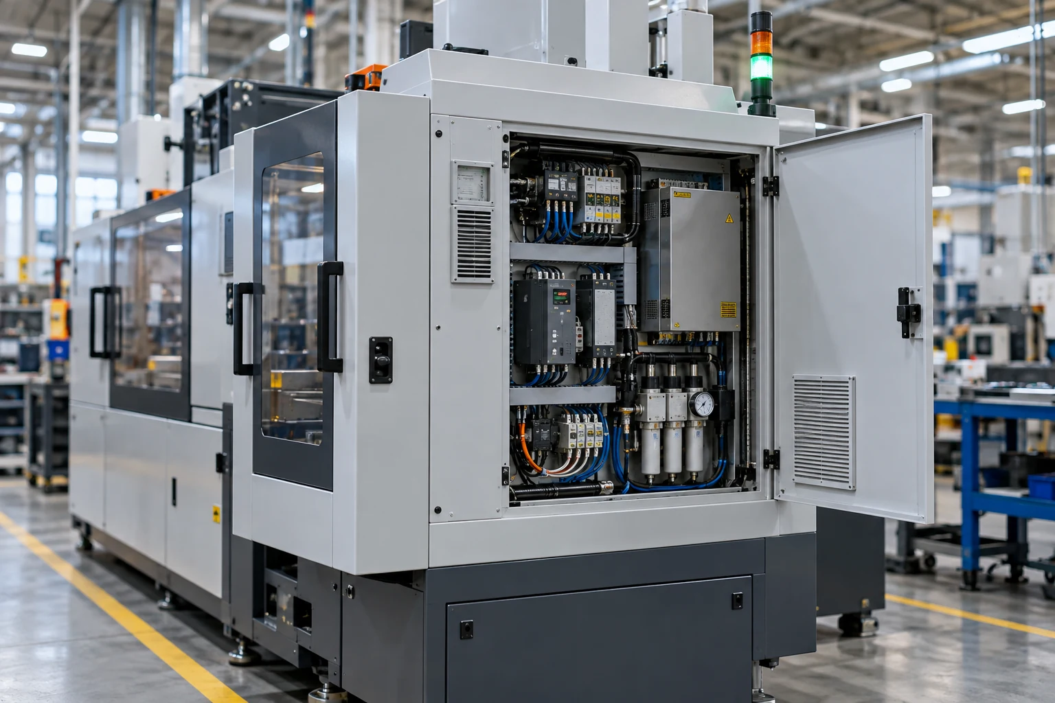
Machine-service area visibility

A machine tool with an external control panel and adjacent service access.

Support authorized staff in reviewing the external machine area during setup, service coordination and routine operation.
View requirements
Define the external viewpoint, machine access points and the viewing arrangement needed by the service team.
Observation scope
Keep the observation scope outside guarded machine functions and identify the visual context required for the service task.
Project checks
Check guards, open doors, operator positions and lighting for their effect on the selected view.
Discuss this application ↗

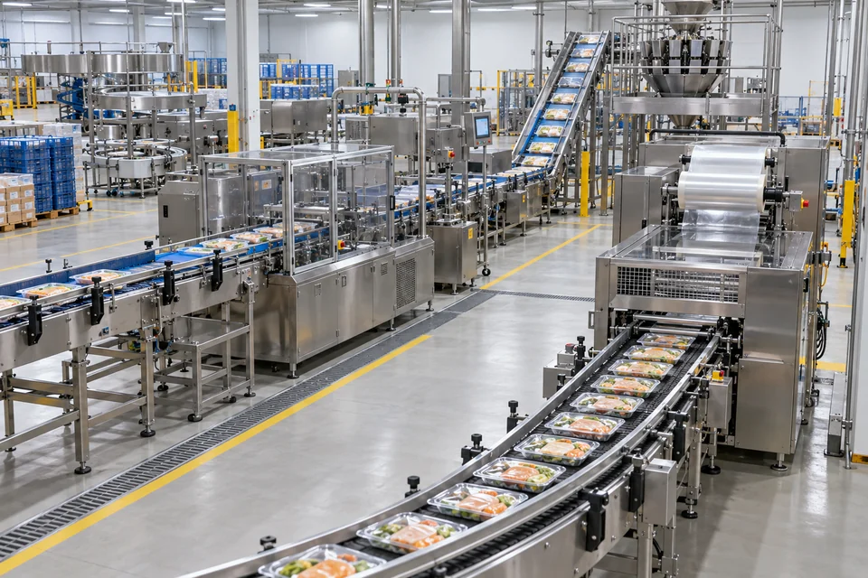
Packaging-area workflow context

Packaging and processing equipment in a food-production environment.

Show the selected packaging area so staff can review the visible workflow and coordinate attendance when required.
View requirements
Specify the packaging zone, working distance and any requested viewing or recording arrangement.
Observation scope
Review the installation location against hygiene, cleaning and access requirements for the production area.
Project checks
Use representative packaging activity to assess glare from surfaces, obstructions and required image detail.
Discuss this application ↗

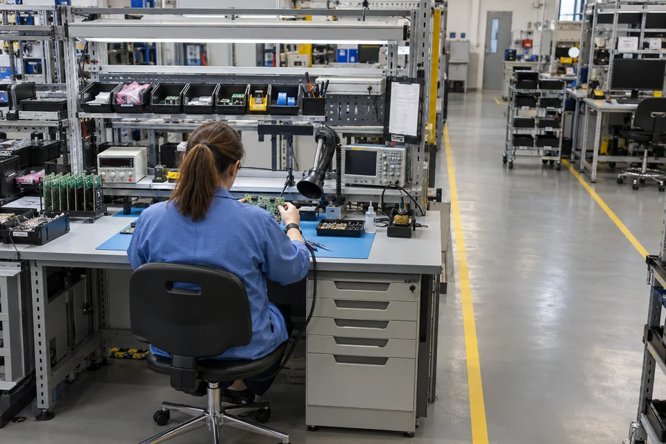
Electronics work-cell context

A technician handling a circuit-board assembly in an electronics work area.

Provide a visual reference for manual handling and service activity around an electronics work area.

View requirements
Define the work-area boundary and the level of general activity detail required for the viewing task.
Observation scope
Use the scene for human workflow context; any board-quality inspection or measurement belongs to a separately specified system.
Project checks
Check bench lighting, handling occlusions and the agreed scope for workplace image access.
Discuss this application ↗
02Warehouses & Logistics5
Warehouse racking and a clear central storage aisle.

Support human review of storage access, goods handling and handover areas. Specify the actual view and the receiving workflow; visual context is separate from stock transactions, temperature records or automated item identification.

Storage-aisle overview

Warehouse racking and a clear central storage aisle.

Give staff a view of a selected warehouse aisle and its access routes for routine operational review.
View requirements
Define aisle length, rack height, observation position and the viewing destination.
Observation scope
Agree which rack-facing and circulation areas need to be visible rather than assuming one viewpoint covers the whole warehouse.
Project checks
Check rack occlusion, changes in stored goods and representative aisle lighting.
Discuss this application ↗

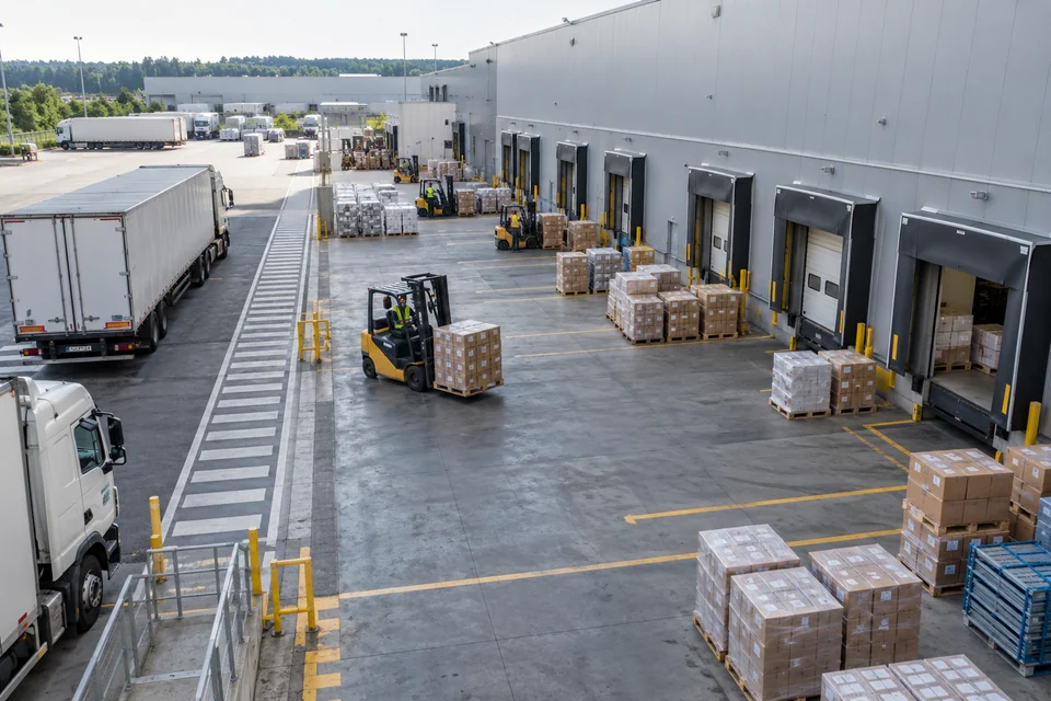
Dispatch staging and handover

A warehouse dispatch staging zone with loading doors, pallets and a clear access route.

Provide visual context for pallets and cartons staged near dispatch doors during the agreed goods-handover workflow.

View requirements
Specify the staging zone, door positions and any requested image-review arrangement.
Observation scope
Coordinate the view with the handover process without treating images as a substitute for dispatch records.
Project checks
Review door-open backlighting, vehicle obstruction and changes in pallet positions.
Discuss this application ↗

Packing and returns work areas

A packing and returns work area with a bench, cartons and adjacent storage.

Support review of visible packing and returns activity around a defined bench and its adjacent storage space.
View requirements
Define the bench view, handling area and authorized receiving viewer or record system.
Observation scope
Frame the general work process; label reading, barcode capture and automatic item verification are separate requirements.
Project checks
Check hand and carton occlusion, surface reflections and the image detail agreed for the task.
Discuss this application ↗

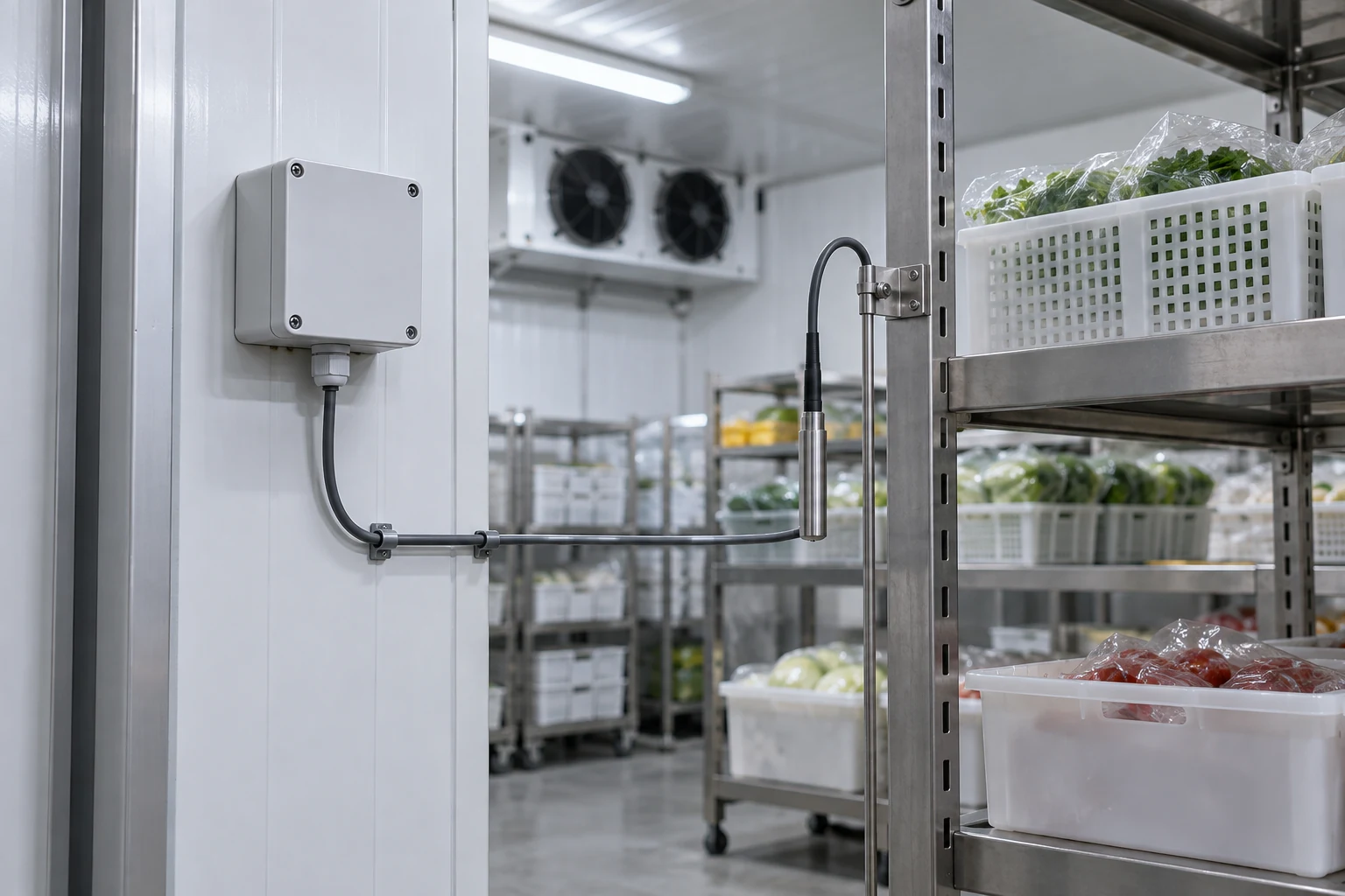
Cold-store access context

A refrigerated storage area with shelving, containers and nearby service equipment.

Show the selected cold-store access or shelving area when staff need visual context alongside the site operating records.

View requirements
Specify the viewpoint, lighting and required image delivery for the storage area.
Observation scope
Qualify the installation for the actual temperature, condensation and cleaning conditions; keep temperature monitoring on its specified sensors.
Project checks
Review door cycles, moisture effects, fogging risk and visibility between stored containers.
Discuss this application ↗

Cold-chain loading context

Refrigerated logistics vehicles and a cold-chain loading environment.

Provide visual context for a defined refrigerated loading or unloading handover area.
View requirements
Define the loading position, vehicle approach and the part of the handover process to be viewed.
Observation scope
Use images to assist human review of the handover; product condition and cold-chain compliance require their own records.
Project checks
Check changing daylight, loading-door positions and obstruction by vehicles and handled goods.
Discuss this application ↗
03Building Entrances & Shared Areas5
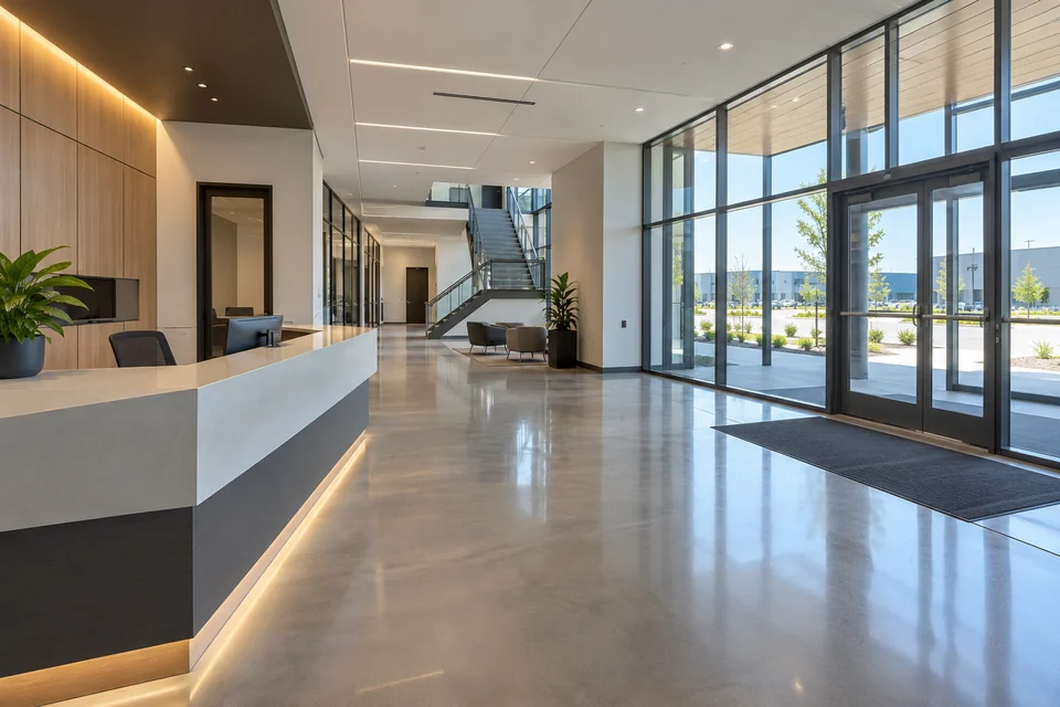
A building entrance lobby with reception space and shared circulation routes.

Plan views of entrances, shared routes and building-service spaces around a defined operational purpose. Agree the scene boundary, authorized access and any recording requirements with the building operator.

Entrance-lobby visibility

A building entrance lobby with reception space and shared circulation routes.

Give authorized staff visual context for an entrance lobby and the shared circulation space serving the building.
View requirements
Define entrance coverage, viewing distance and the receiving system required by the building operator.
Observation scope
Set the view around the agreed common area and avoid unrelated private spaces or unnecessary close personal detail.
Project checks
Assess entrance backlighting, reflections from glazing and obstruction around the reception area.
Discuss this application ↗

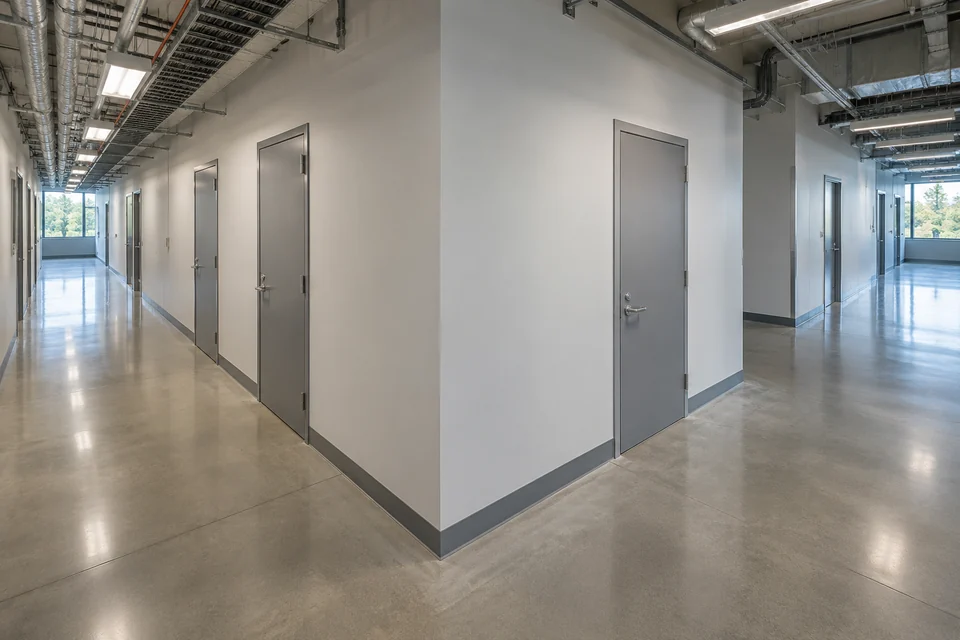
Shared-corridor observation

A shared building corridor with service-room doors and a clear junction.

Support visual review of a selected corridor junction and common service-room access points.
View requirements
Specify the corridor boundary, door positions and the intended observation viewpoint.
Observation scope
Agree the purpose and image-access scope for the shared route; private-room interiors remain outside the requested view.
Project checks
Check changes in corridor lighting, opening doors and the detail needed at the far end of the scene.
Discuss this application ↗

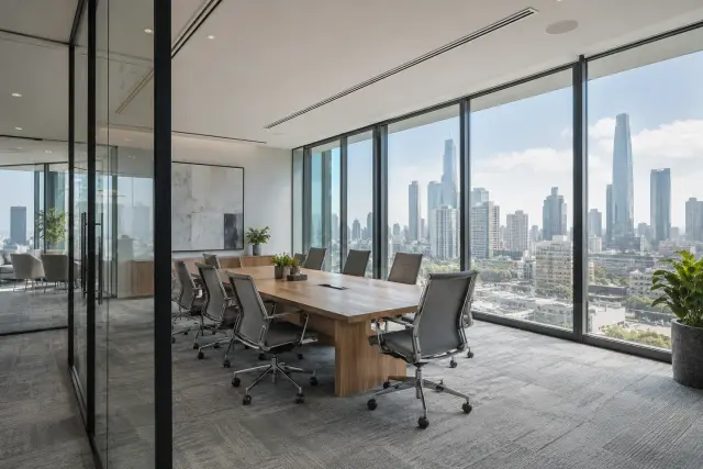
Facilities shared-space review

A shared office workspace with meeting furniture and large windows.

Provide visual context for a shared building workspace used for facilities coordination and service attendance.
View requirements
Define the common operational area and any requested connection to the authorized viewing workflow.
Observation scope
Review the view with the building operator so desks, displays and unrelated personal information are not included unnecessarily.
Project checks
Check daylight variation, screen reflections and the agreed scene boundaries.
Discuss this application ↗

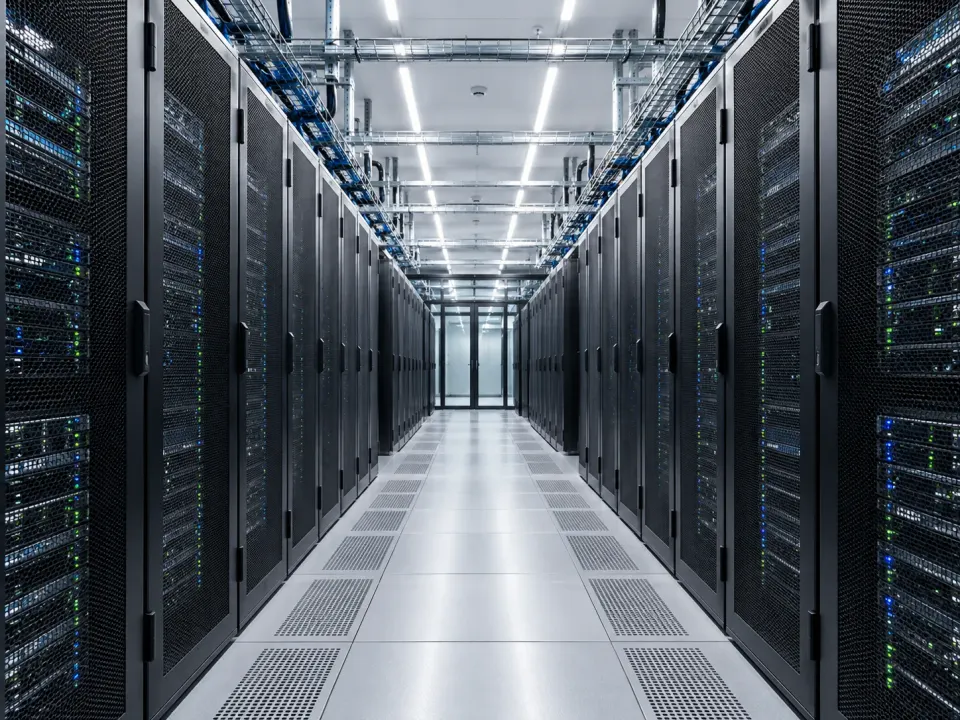
Server-room service access

Server racks and a service aisle in a data-centre equipment room.

Give authorized facilities staff visual context for a selected server-room aisle or service-access area.
View requirements
Specify the aisle, doorway and receiving viewer needed for the facilities task.
Observation scope
Frame access and service activity while protecting unrelated display contents and the separate IT-security process.
Project checks
Review rack occlusion, room lighting, installation access and the local environmental conditions.
Discuss this application ↗

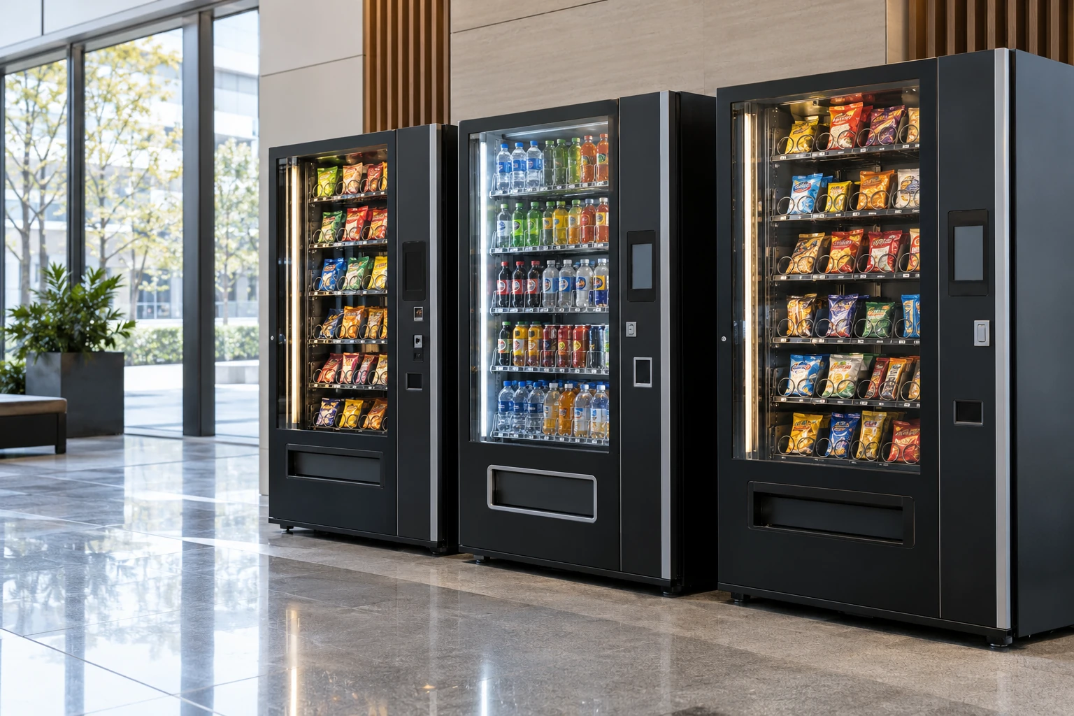
Shared self-service areas

Self-service vending machines in a bright shared building area.

Support human review of the common area around self-service equipment within a building.
View requirements
Define the equipment-front area, nearby circulation route and required image-review destination.
Observation scope
Focus on the agreed operational space; payments, customer identification and equipment transactions remain separate systems.
Project checks
Check display reflections, window backlighting and obstruction during normal equipment use.
Discuss this application ↗
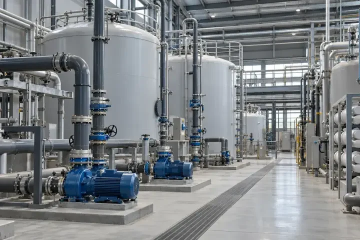
04Plant Rooms & Utilities5
Pumps, valves and pipework inside a building utility room.

Add visual context around visible equipment and service access in utility spaces. Define the observation location and environment; measured temperature, pressure, electrical condition and dedicated alarms remain separate from camera images.

Pump-room overview

Pumps, valves and pipework inside a building utility room.

Provide a view of the selected pump-room equipment area and service route for routine human review.
View requirements
Specify the pumps and access space to be included and the viewing arrangement required by the operator.
Observation scope
Use images to understand visible site context alongside the station instrumentation and service procedure.
Project checks
Check equipment occlusion, reflections from pipework, room lighting and moisture at the mounting position.
Discuss this application ↗

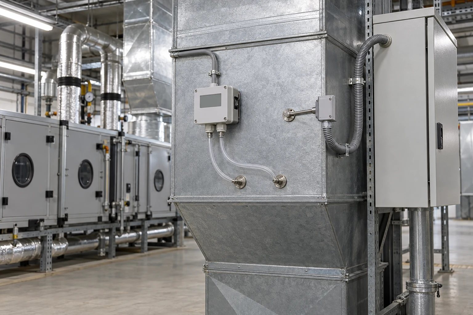
HVAC service-area context

Air-handling equipment and protected building-services enclosures.

Give facilities staff visual context for an air-handling service area before coordinating attendance.
View requirements
Define the equipment-front view and the required route for staff to access the images.
Observation scope
Frame the service space and visible equipment surroundings; airflow, thermal condition and control status require their own measurements.
Project checks
Assess vibration at the installation, local lighting, door positions and maintenance access.
Discuss this application ↗

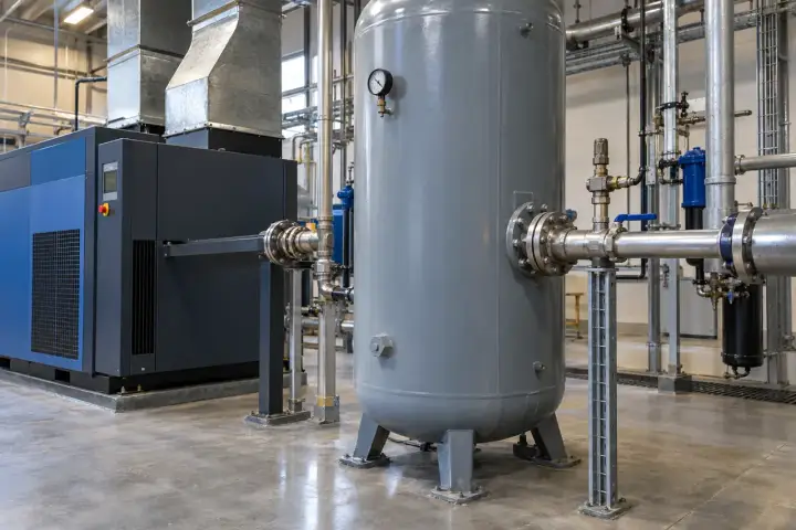
Compressed-air utility areas

Compressed-air equipment, an air receiver and connected service pipework.

Support review of the visible surroundings of compressor and air-receiver equipment.
View requirements
Specify the equipment area, observation distance and any requested review or record workflow.
Observation scope
Set the view around the approved service area rather than using appearance as a pressure or equipment-health measurement.
Project checks
Check vibration exposure, glare, equipment shielding and the normal lighting conditions.
Discuss this application ↗

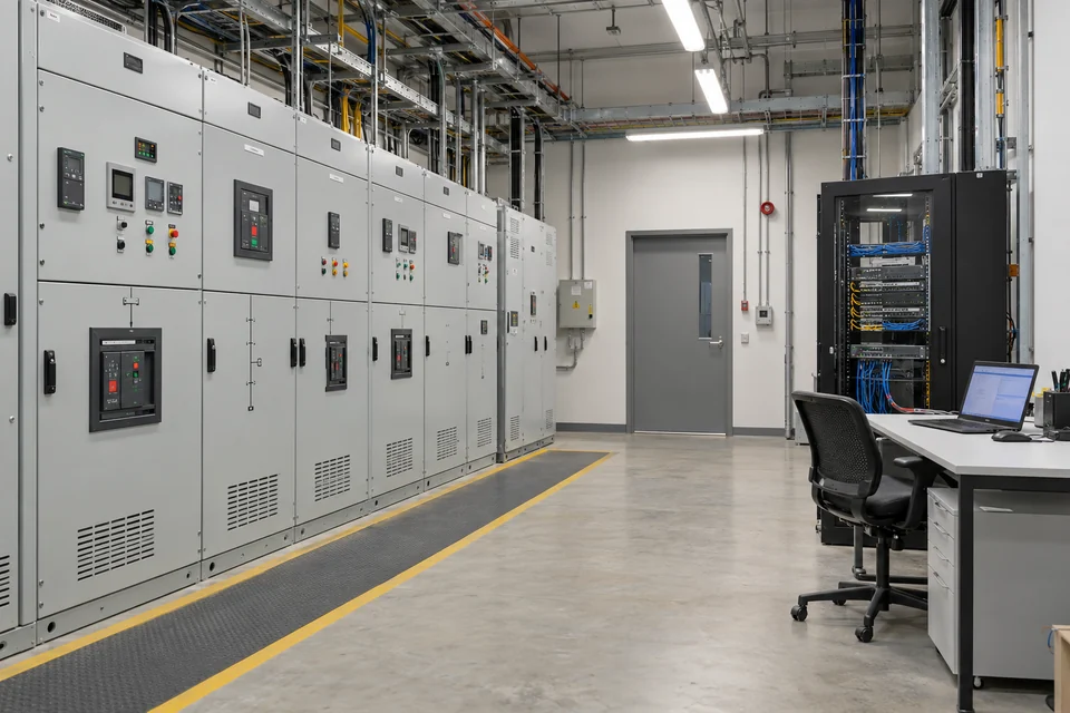
Electrical service-room visibility

An electrical service room with closed switchgear and a separate maintenance workstation.

Provide a visual reference for an electrical service room and its approved maintenance access area.
View requirements
Define a viewpoint outside electrical exclusion zones and the required receiving viewer.
Observation scope
Agree access and review responsibilities with the electrical-site operator; switching and protective functions remain within their approved systems.
Project checks
Check location approval, cabinet doors, lighting and installation clearances.
Discuss this application ↗

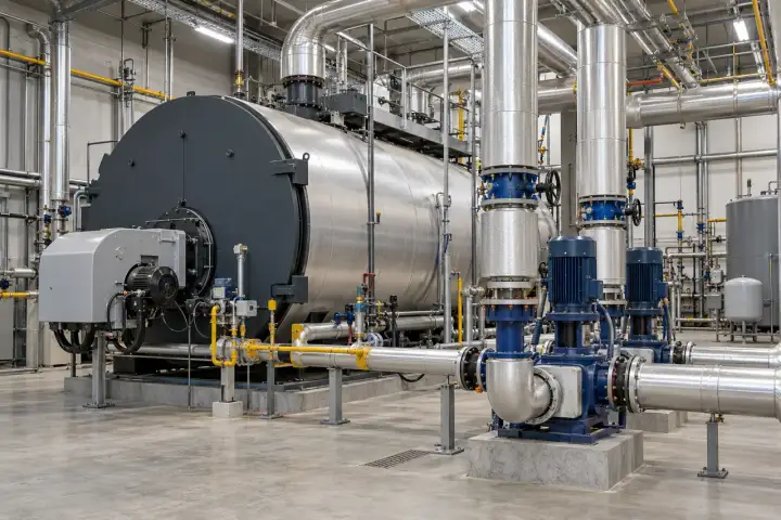
Heating and hot-water service context

Heating and hot-water service equipment with insulated pipework.

Show the visible service area around heating or hot-water plant when staff need operational context.
View requirements
Define the pipework area, safe observation position and required image-delivery arrangement.
Observation scope
Keep the requested view separate from temperature, pressure and protective-trip measurements.
Project checks
Review heat exposure, steam or condensation, access restrictions and visibility under normal operation.
Discuss this application ↗
05Energy & Remote Facilities5
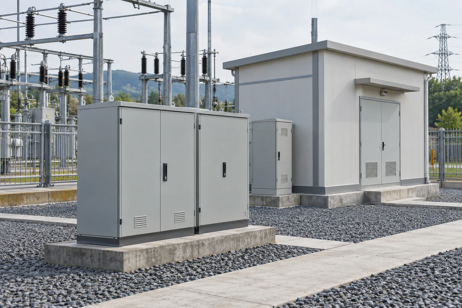
Substation service enclosures and adjacent outdoor electrical infrastructure.

Develop visual-observation tasks for selected energy and unattended facilities. Confirm the mounting location, environmental suitability, power and communication design for the actual project before assigning the camera to an outdoor or restricted installation.

Substation service-area context

Substation service enclosures and adjacent outdoor electrical infrastructure.

Give authorized staff a view of an approved auxiliary service area within a substation facility.
View requirements
Specify the visible area, separation from restricted equipment and the receiving viewing arrangement.
Observation scope
Define the task as supporting visual context; utility approvals, protection systems and safety decisions are separate project requirements.
Project checks
Check site permissions, mounting environment, electromagnetic conditions and the required scene detail.
Discuss this application ↗

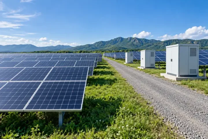
Solar-site service-route visibility

Solar arrays, service enclosures and an access route at a generation site.

Support review of a selected access route and equipment-service area at a solar installation.
View requirements
Define the route, nearby equipment and observation distance for the requested view.
Observation scope
Assess the complete outdoor installation and the site viewing workflow rather than assuming direct exposure is supported by the reference enclosure.
Project checks
Check changing sunlight, shadows, dust, mounting stability and any obstructions along the route.
Discuss this application ↗

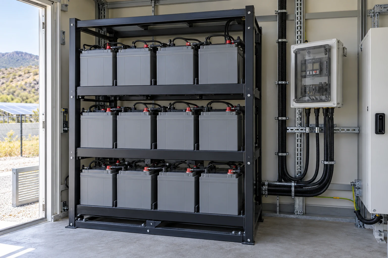
Battery-installation service context

Battery modules and adjacent protected service equipment.

Provide visual context for approved service activity around battery-installation auxiliary equipment.
View requirements
Specify the visible service area and the viewing destination required by the facility operator.
Observation scope
Use the scene alongside the battery-management and protection systems; images do not replace battery-state or fire measurements.
Project checks
Review installation location, restricted areas, lighting and the site’s qualification requirements.
Discuss this application ↗

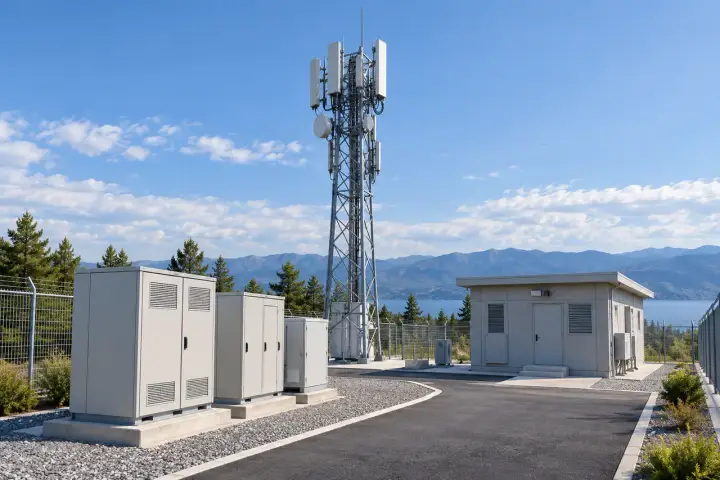
Telecom-site service access

Telecommunications equipment and protected service enclosures at a site.

Show a selected communications-site service area to assist authorized staff in reviewing visible conditions and attendance.
View requirements
Define equipment access points, the observation viewpoint and the requested means of image delivery.
Observation scope
Agree the complete power and communication arrangement for the camera project and the site access procedure.
Project checks
Check enclosure conditions, line of sight, local lighting and mounting exposure.
Discuss this application ↗

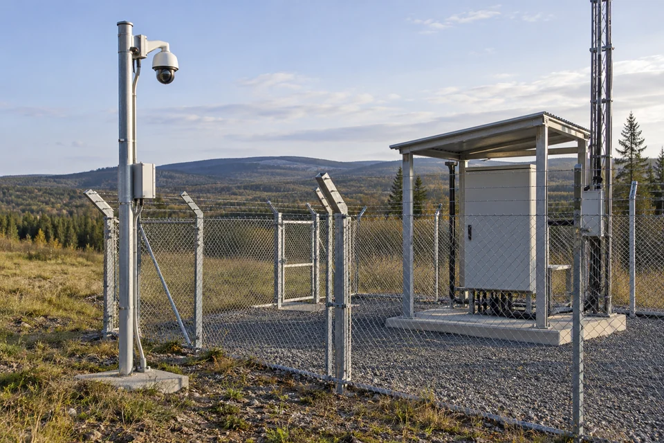
Remote-facility perimeter context

A remote facility boundary with fencing, a service entrance and protected site equipment.

Provide a view of the selected boundary or service entrance of an unattended facility for human review.
View requirements
Define the part of the perimeter to be observed and the required receiving workflow.
Observation scope
Agree any access or recording process with the site operator; automatic intrusion classification is not part of this reference description.
Project checks
Review light variation, vegetation or fence occlusion and the environmental conditions at the proposed mounting location.
Discuss this application ↗
06Water & Environmental Sites5
A water-service manifold with pipework, valves and nearby maintenance access.

Use visual context to support the operation of accessible water and environmental-service areas. Specify the location and viewing objective; water quality, level, flow and other process measurements remain the responsibility of their instruments and control systems.

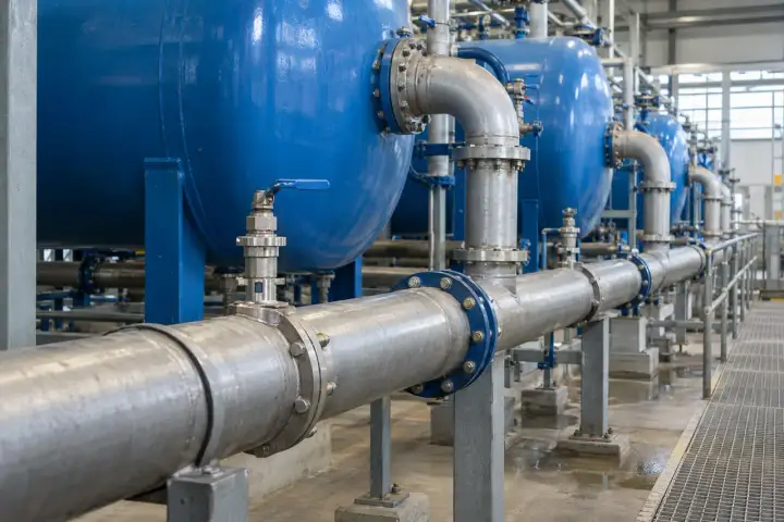
Water-service equipment context

A water-service manifold with pipework, valves and nearby maintenance access.

Show a selected manifold and surrounding service area to assist staff in reviewing visible installation conditions.
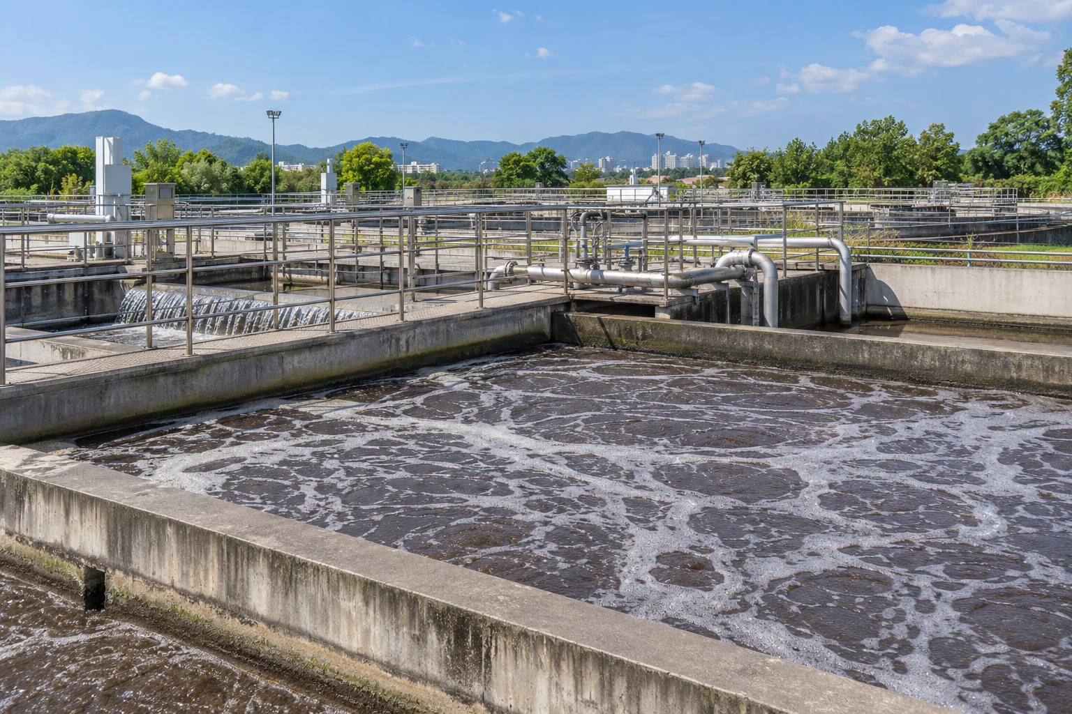
View requirements
Define the pipework and access space to be observed and the viewing destination.
Observation scope
Agree which visible conditions matter to the service task without treating appearance as a flow or water-quality measurement.
Project checks
Check pipework occlusion, reflections, access restrictions and moisture at the installation point.
Discuss this application ↗

Treatment-site walkway overview

Wastewater-treatment basins with operational walkways and service areas.

Provide a visual overview of a selected treatment-site walkway and adjacent equipment area.
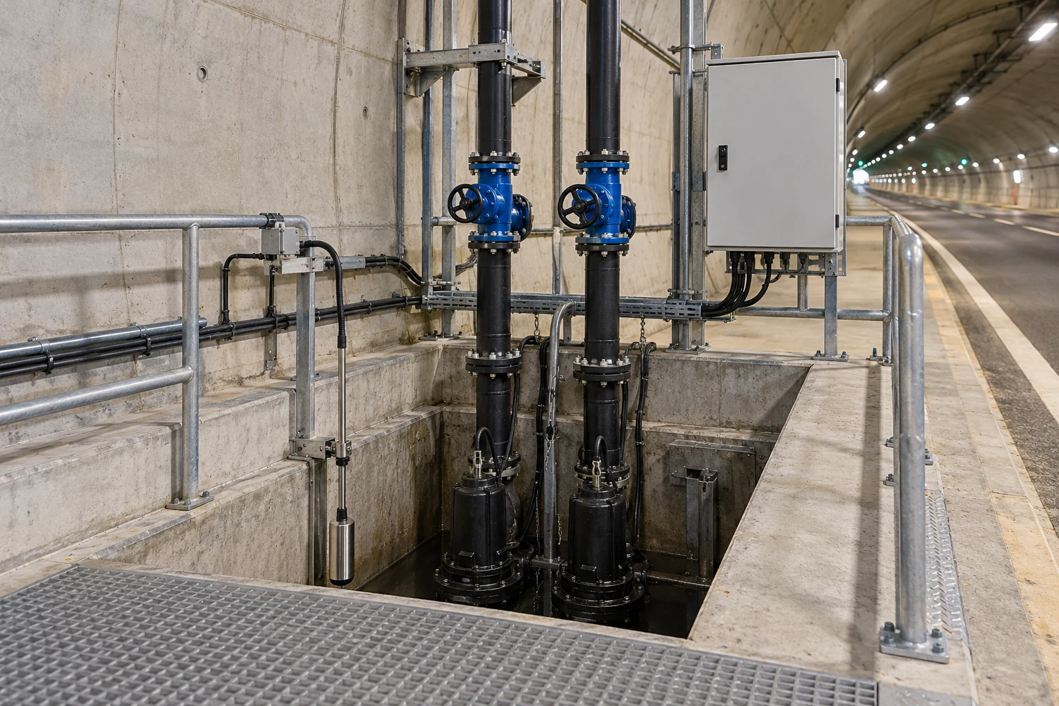
View requirements
Specify the walkway, observation distance and required image-delivery arrangement.
Observation scope
Coordinate the view with the site’s operating procedure and qualify the installation for its actual environmental exposure.
Project checks
Check sunlight, reflections from water, railings and changing obstruction along the selected route.
Discuss this application ↗

Drainage-station service context

Drainage-pump equipment and protected service facilities inside a utility structure.

Support staff in reviewing visible access conditions around an approved drainage-station service area.
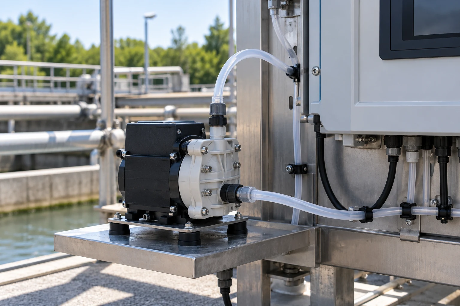
View requirements
Define the equipment-access zone and any requested means of viewing or reviewing images.
Observation scope
Locate the installation according to flood and moisture conditions; pumping decisions and flood alarms remain separate functions.
Project checks
Review mounting height and access, light variation, moisture exposure and potential scene obstruction.
Discuss this application ↗

Sampling-system service visibility

A sampling-system installation with instruments, tubing and a service enclosure.

Provide visual context for a sampling-system service area during authorized attendance and routine review.
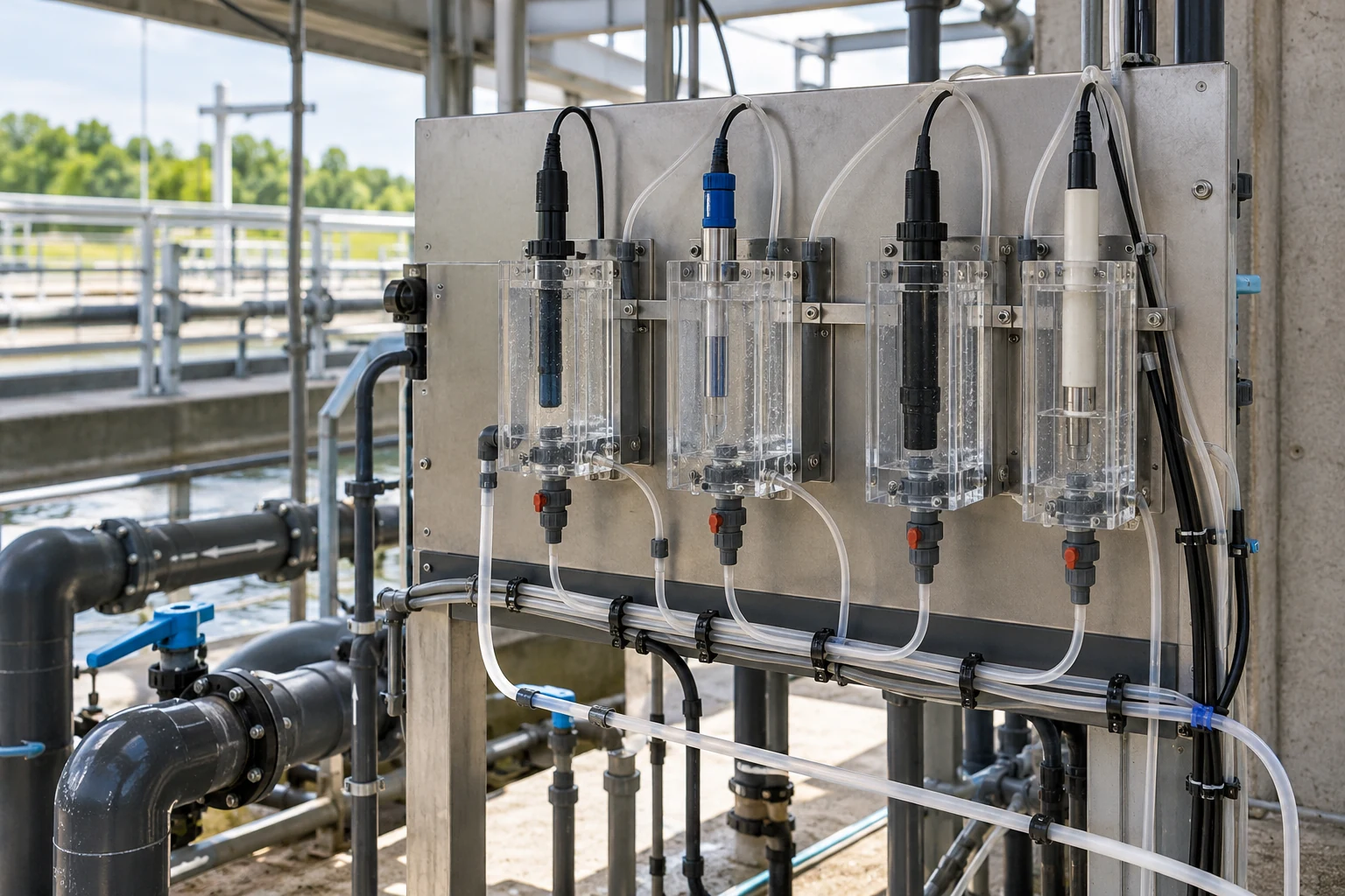
View requirements
Specify the instrument service space and the level of general activity detail required.
Observation scope
Use the view to support the service workflow; sample analysis and process alarm decisions remain with their specified systems.
Project checks
Check cabinet-door obstruction, tubing glare, lighting and any location qualification requirements.
Discuss this application ↗

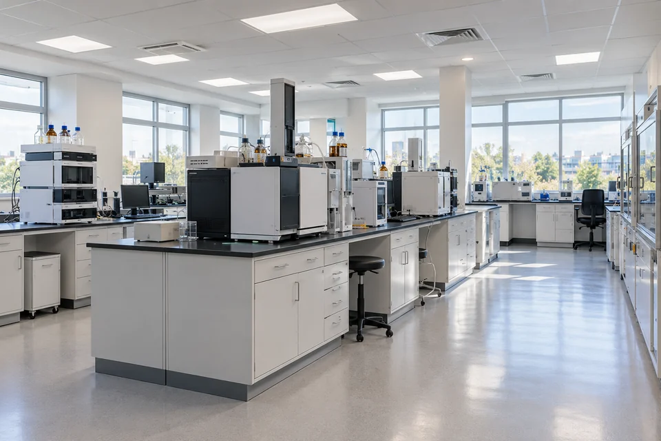
Water-quality equipment-area context

Water-quality instrument equipment arranged in a protected service rack.

Show the selected instrument-rack surroundings when staff need context for a service request or site review.
View requirements
Define the equipment area and the requested receiving-view arrangement.
Observation scope
Keep analytical readings and calibrated measurements within the instrument data system; agree any human-visible detail as an acceptance objective.
Project checks
Review reflections, cable or instrument occlusion, room lighting and service access.
Discuss this application ↗
07Laboratories & Controlled Workspaces5
An orderly laboratory workspace with bench instruments and clear access aisles.

Plan human visual review of authorized work areas, storage access and outer handover spaces. Define privacy, process information and installation requirements with the operator; the reference is not a laboratory measurement, automated quality-inspection or cleanroom-qualified camera specification.

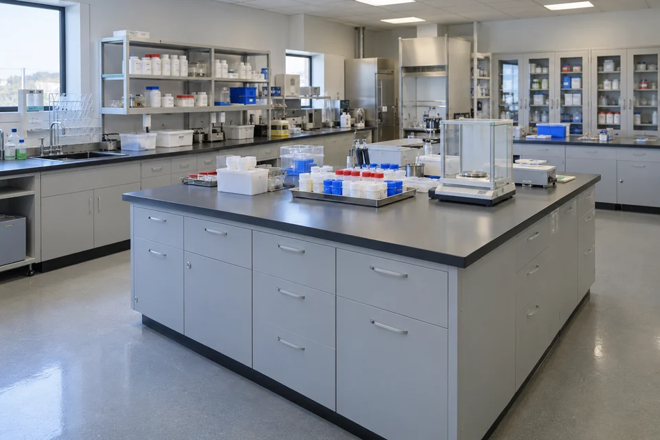
Laboratory workspace overview

An orderly laboratory workspace with bench instruments and clear access aisles.

Provide a general view of the agreed laboratory workspace to support activity review and service coordination.
View requirements
Define the bench area, access aisles and receiving viewer required for the task.
Observation scope
Frame general activity within the approved scope and protect unrelated displays, personal information and confidential work.
Project checks
Assess instrument occlusion, bench lighting and the level of visible context required in representative conditions.
Discuss this application ↗

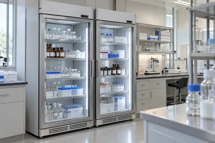
Sample-preparation workflow context

A sample-preparation bench with closed containers and organized laboratory equipment.

Support human review of the visible sample-preparation area and its surrounding workspace.
View requirements
Specify the bench coverage, observation distance and any requested review or recording workflow.
Observation scope
Use images for process context; sample identity, chain-of-custody and analytical results remain within the laboratory’s documented systems.
Project checks
Check hand and container occlusion, surface glare and the agreed boundaries of the recorded scene.
Discuss this application ↗

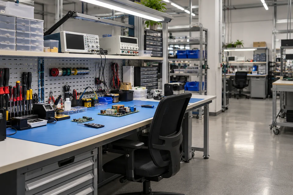
Laboratory storage-access context

Laboratory storage cabinets and organized containers in a controlled workspace.

Give authorized staff a view of the selected laboratory storage area and its access space.
View requirements
Define the cabinets, shelves and access route to be included in the view.
Observation scope
Coordinate the image-access and any retention arrangements with the storage procedure; inventory and environmental records remain separate.
Project checks
Review shelf occlusion, opening doors, available lighting and the installation conditions.
Discuss this application ↗

Electronics-bench activity context

An electronics workbench with tools, test equipment and circuit assemblies.

Provide visual context for manual work and service activity at an electronics bench.
View requirements
Define the bench boundary and the general activity detail required for the authorized viewer.
Observation scope
Use the selected scene to support workflow review; electrical testing, component identification and quality measurement require their own methods.
Project checks
Check tool and hand occlusion, task lighting and unwanted inclusion of confidential display content.
Discuss this application ↗

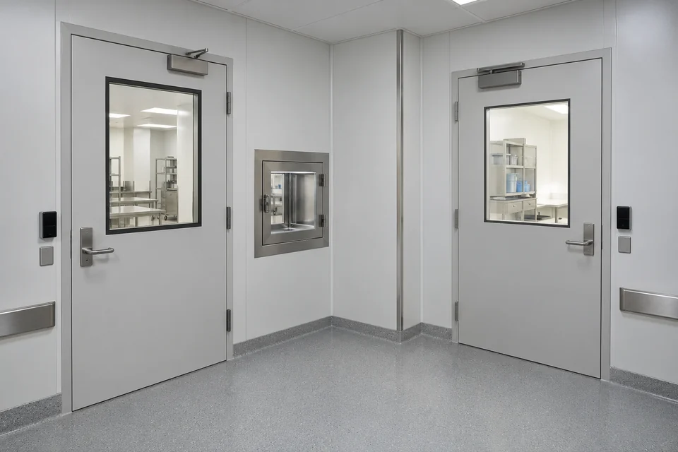
Controlled-room outer handover

An outer controlled-room entry with a material pass-through and service access space.

Show an agreed outer entry or material-handover area serving a controlled workspace.
View requirements
Specify the outer-side viewpoint, doors and pass-through area required for observation.
Observation scope
Qualify the mounting location and data-handling scope with the site operator; cleanroom or containment approvals require separate evidence.
Project checks
Review door movements, reflections, cleaning practices and the boundaries of the requested view.
Discuss this application ↗
08Transport & Site-Service Areas5
An industrial site entrance with a guard point and vehicle approach.

Support human review of entrances, yards, loading points and maintenance access from an approved installation position. Define coverage and environmental requirements for the project; the examples do not specify automatic plate recognition, traffic enforcement or safety-control functions.

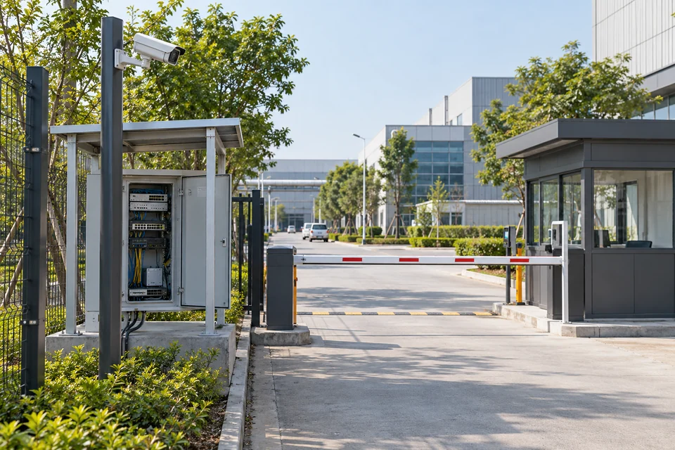
Site-entrance activity context

An industrial site entrance with a guard point and vehicle approach.

Give authorized staff a view of the agreed entrance area and the adjacent service approach.
View requirements
Define entrance coverage, observation distance and the receiving viewing workflow.
Observation scope
Coordinate image access with the site’s entrance procedure; identity checks and gate movement remain with their respective systems.
Project checks
Assess approach lighting, passing-vehicle obstruction, mounting exposure and the required scene detail.
Discuss this application ↗

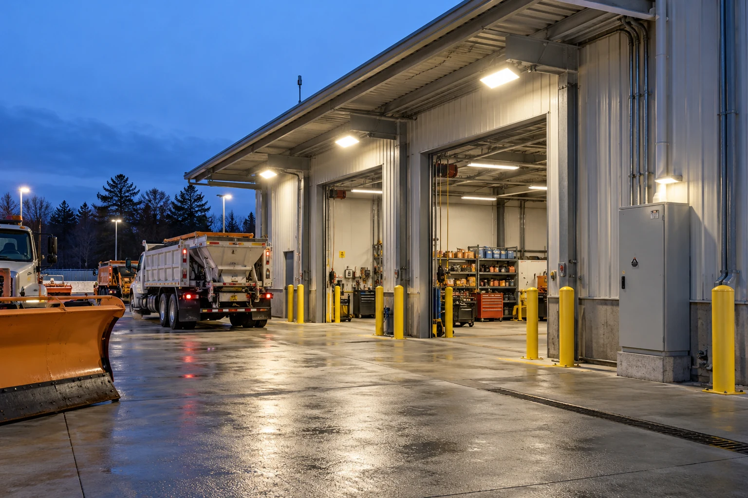
Loading-bay activity review

An industrial loading bay with service doors, vehicles and artificial lighting.

Provide visual context around a selected loading bay and nearby service route during goods handling.

View requirements
Specify loading positions, door coverage and the requested review or recording destination.
Observation scope
Frame the agreed handover activity and assess the lighting design for the actual operating periods.
Project checks
Review vehicle occlusion, open-door backlighting, artificial lighting and visibility of the selected work zone.
Discuss this application ↗

Logistics-yard operational overview

A container logistics yard with freight-handling equipment and service routes.

Support a general visual review of the selected yard area and its service activity.
View requirements
Define the area, observation distance and receiving viewer needed by the yard operator.
Observation scope
Agree the useful operational context and any additional viewpoints required; the scene is not an automatic vehicle-tracking function.
Project checks
Check changing goods positions, large-equipment obstruction, lighting and installation exposure.
Discuss this application ↗

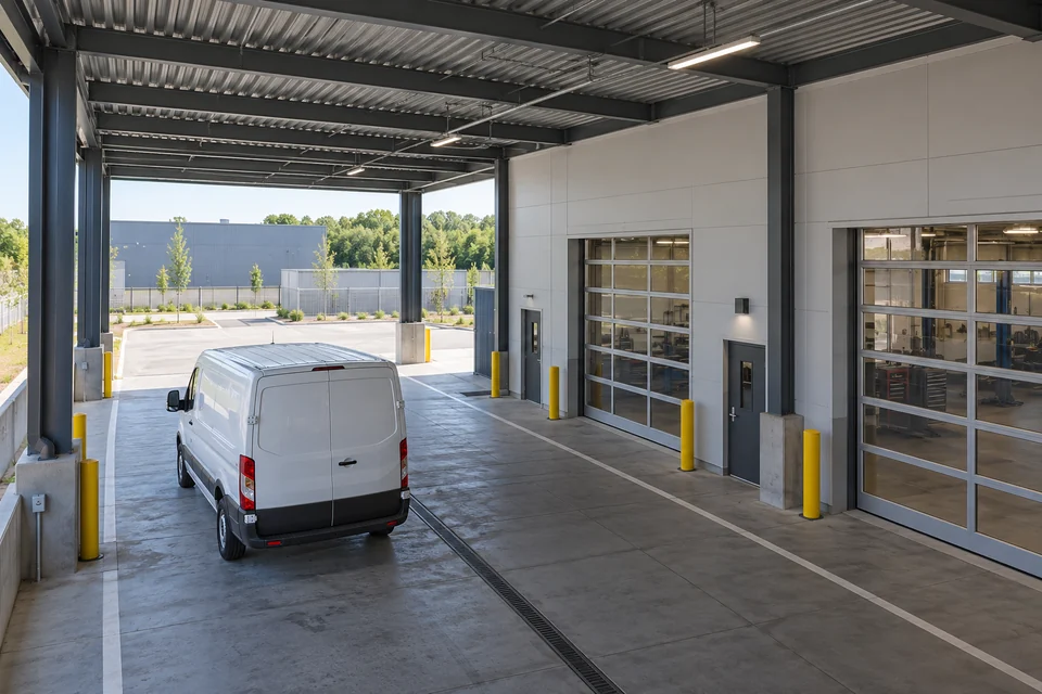
Covered vehicle-service entrances

A covered vehicle-service entrance with a maintenance bay and separated pedestrian route.

Show an agreed covered entrance and maintenance-bay approach to assist service coordination.
View requirements
Specify the sheltered viewpoint, vehicle approach and adjacent pedestrian route to be included.
Observation scope
Review the view as an operational aid; workshop access, vehicle control and safety procedures remain independently defined.
Project checks
Check bright-to-shaded transitions, parked-vehicle obstruction and the conditions at the mounting location.
Discuss this application ↗

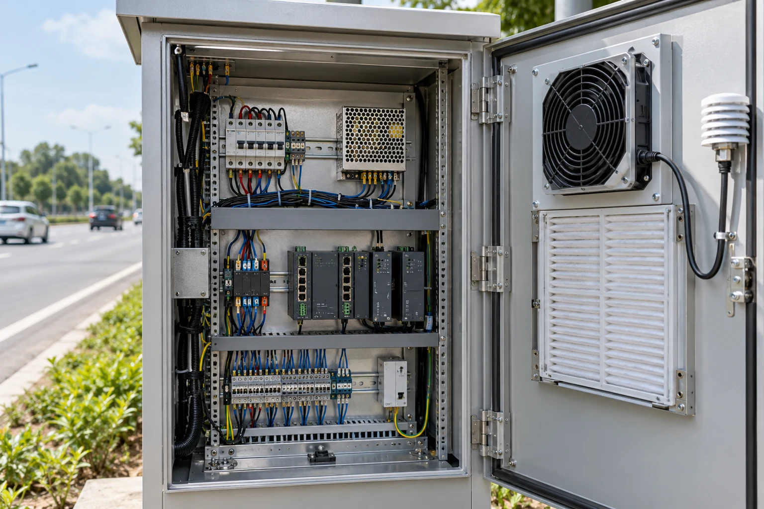
Roadside service-access context

A roadside service cabinet beside urban transport infrastructure.

Provide visual context for an approved roadside equipment-service point and its immediate access area.

View requirements
Define the cabinet-service area, observation position and required image-delivery workflow.
Observation scope
Coordinate the installation with the site authority and keep the purpose within the documented maintenance task.
Project checks
Check environmental exposure, passing-traffic obstruction, cabinet-door positions and safe maintenance access.
Discuss this application ↗

REFERENCE & PROJECT CONFIGURATION

A design reference.
A project-specific specification.

This H100-HTC1800 customization reference organizes the camera requirements for your project. The table organizes the imaging, installation and system requirements to agree for the project. Numeric performance, electrical ratings and supported functions are defined in the approved configuration documents.

Product reference

H100-HTC1800 — Product reference
Product modelH100-HTC1800
Product visualHitelecom dome-camera reference, as illustrated.
Document scopeCustom camera reference and project-configuration framework; not a fixed-performance specification.

Optics and imaging

H100-HTC1800 — Optics and imaging
Observation targetDefine the visible equipment, activity or site condition and the detail required for operator review.
Coverage and lensSpecify scene width, target distance, mounting height and required coverage; agree the lens and viewing arrangement.
Image parametersAgree the image sensor, output resolution, frame-rate behaviour and exposure requirements for the selected configuration.
Lighting evaluationAssess representative lighting, shadows, reflections and relevant operating periods using the agreed sample or configuration.

Power and connection

H100-HTC1800 — Power and connection
SupplyDefine the supply method, rated electrical values, consumption and protection requirements in the project specification.
InterfacesAgree the physical connections, signal or network interface, connector and cable arrangement for the receiving equipment.
Installation wiringObtain the approved wiring schedule, earthing requirements and associated device power budget.

Viewing and system integration

H100-HTC1800 — Viewing and system integration
Image workflowDefine live viewing, image transfer or recording requirements and the equipment responsible for each function.
Receiver compatibilityVerify the agreed output method, formats, protocols and supported functions with the selected receiver.
Recording and accessAgree the recording location, retention needs, authorized access and operating responsibilities.
Software scopeIdentify any required integration work and document the functions included in the delivered project.

Mechanical and environmental

H100-HTC1800 — Mechanical and environmental
Camera assemblyDome-style product visual. Agree the supplied enclosure, mounting components and service arrangement.
Installation locationReview mounting surface, coverage, obstructions, cable entry and maintenance access.
Environmental requirementsSpecify operating conditions, moisture, dust, cleaning and mechanical exposure for the completed assembly.
Qualification evidenceAgree any required ingress, impact, EMC, safety or sector-specific evidence for the supplied configuration.

Customization and acceptance

H100-HTC1800 — Customization and acceptance
Project inputsScene photographs, observation target, distances, mounting position, lighting, receiving equipment and installation requirements.
Design approvalRecord the selected hardware, imaging parameters, electrical and interface definition, product identification and any software scope.
Acceptance checksAgree scene coverage, usable image detail, lighting and motion conditions, receiver operation, power behaviour and installation checks.
Delivery documentsApproved configuration record, installation instructions, test evidence and maintenance information within the agreed supply scope.

Specify the completed camera assembly and receiving workflow for the intended installation. Validate image quality, interfaces and environmental requirements against the agreed acceptance criteria.

IMAGE PATH & SYSTEM INTEGRATION

From the scene. To the receiving system.

Define the complete image path for the project: the camera configuration, connection, receiving equipment and the people who use the images. Viewing, recording, remote access and any associated notifications are system requirements to allocate and verify with the selected equipment and software.

Image use: agree the required viewing or recording workflow, receiving equipment and available connection. Define the output method and supported functions in the configuration proposal.

Installation: coordinate power, cable routing, mounting and local lighting with the camera assembly. Review the actual environment and service access before approving the location.

Acceptance: evaluate coverage and useful image detail with representative scenes, motion and lighting. Document receiver compatibility, authorized access and the delivered configuration.

ANSWERS FOR YOUR PROJECT

Practical questions.
Before you specify the camera.

Answers for optics, scene conditions, power, receiving systems and the scope of camera customization.

What is H100-HTC1800?

H100-HTC1800 is a dome-camera reference for custom industrial-site visual monitoring projects. The project specification establishes the supplied imaging configuration, electrical details, connection method and supported functions.

Does the model name identify a resolution or viewing angle?

No resolution, field of view or image-sensor specification is defined by the model name on this page. Agree those parameters against the observation task and record them in the approved configuration documents.

How should the lens and coverage be selected?

Provide the target distance, scene width, mounting height, viewing direction and the detail an operator must see. Review obstructions and representative scenes, then evaluate the agreed lens and camera configuration at the intended position.

How are resolution and frame rate specified?

Start with the required image detail and movement in the scene. Agree resolution, frame-rate behaviour, exposure and the receiving-system requirements together. Evaluate useful image detail under the relevant conditions rather than selecting only by a headline pixel count.

Are low-light, infrared or automatic day/night functions included?

Define the lighting conditions and any required operating periods in the project brief. The configuration proposal identifies the imaging functions and any associated illumination included in the supply. The illustrated housing alone does not specify these functions or their performance.

Which power supply and connection method does it use?

The supplied visual does not establish a rated supply, electrical connector or communications interface. Specify the available site power, receiver and connection requirements, then obtain the approved electrical values, wiring schedule and interface definition for the selected configuration.

Can it work with a recorder, existing video system or cloud platform?

Identify the intended receiving system and required viewing or recording workflow. Review the output method, formats, protocols, access requirements and any integration work in the proposal, then validate the agreed functions together. No particular recorder, protocol or built-in cloud service is specified by this reference alone.

Does it provide AI analytics or machine-vision inspection?

This page describes visual monitoring projects for operator review. Automated classification, identification, counting, defect detection or dimensional measurement would require a separately defined and validated development scope; they are not established functions of this camera reference.

Can images be reviewed alongside sensor events?

A project may define a workflow in which authorized staff review images together with external measurement records or events. Agree the receiving software, data interfaces, time relationship and user workflow before implementation. Camera images do not replace the independent measurement or protection system.

Can it be installed outdoors or in a demanding industrial location?

Review the complete installation against temperature, moisture, dust, cleaning, mechanical exposure and any site-specific qualification requirements. Confirm the enclosure, mounting and supporting evidence for the final assembly before selection. A dome-style appearance does not establish an ingress, impact or hazardous-area rating.

Are the application photographs examples of camera image quality?

They illustrate the observation environments and project tasks. They are not recorded H100-HTC1800 footage, installed customer examples or demonstrations of image resolution, low-light performance or analytics. Use representative sample evaluation to confirm actual imaging performance.

What should a camera customization enquiry include?

Share scene photographs, the observation target, required detail, distances, mounting position and lighting conditions. Add the available power, receiving system, connection needs, environmental requirements, expected quantity and delivery documents so the proposal can define configuration, development and acceptance scope.

LET'S TALK ABOUT YOUR PROJECT

Your observation task.
A defined camera configuration.

Share the scene and what the image must help your team understand. Include mounting conditions, lighting, available power and the intended receiving system so we can review the H100-HTC1800 reference and define the proposed camera configuration and validation scope.

sales@hitelecom.cn ↗

H100-HTC1800 Custom Dome Camera

Review your brief, then send it with your email app.